7.4
SEL-2032 Communications Processor Instruction Manual Date Code 20120126
Settings
Port Configuration (SET P) and Communication Settings
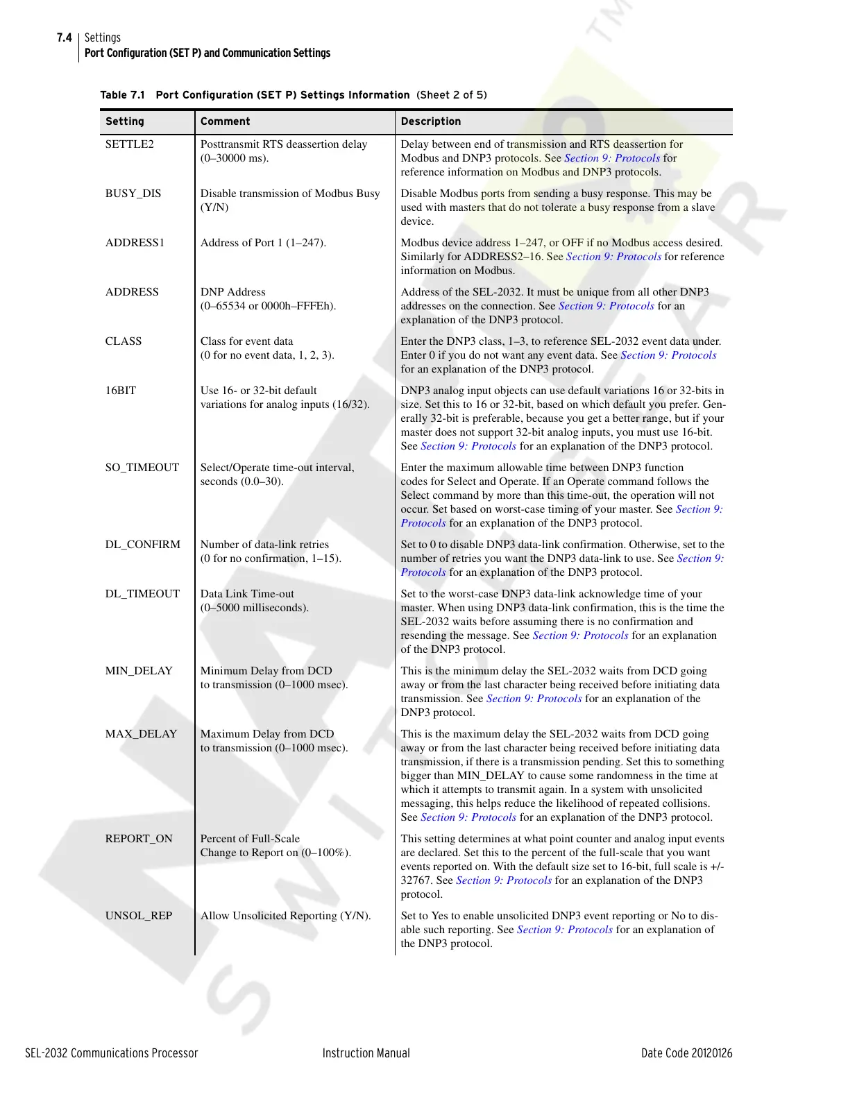
SETTLE2 Posttransmit RTS deassertion delay
(0–30000 ms).
Delay between end of transmission and RTS deassertion for
Modbus and DNP3 protocols. See Section 9: Protocols for
reference information on Modbus and DNP3 protocols.
BUSY_DIS Disable transmission of Modbus Busy
(Y/N)
Disable Modbus ports from sending a busy response. This may be
used with masters that do not tolerate a busy response from a slave
device.
ADDRESS1 Address of Port 1 (1–247). Modbus device address 1–247, or OFF if no Modbus access desired.
Similarly for ADDRESS2–16. See Section 9: Protocols for reference
information on Modbus.
ADDRESS DNP Address
(0–65534 or 0000h–FFFEh).
Address of the SEL-2032. It must be unique from all other DNP3
addresses on the connection. See Section 9: Protocols for an
explanation of the DNP3 protocol.
CLASS Class for event data
(0 for no event data, 1, 2, 3).
Enter the DNP3 class, 1–3, to reference SEL-2032 event data under.
Enter 0 if you do not want any event data. See Section 9: Protocols
for an explanation of the DNP3 protocol.
16BIT Use 16- or 32-bit default
variations for analog inputs (16/32).
DNP3 analog input objects can use default variations 16 or 32-bits in
size. Set this to 16 or 32-bit, based on which default you prefer. Gen-
erally 32-bit is preferable, because you get a better range, but if your
master does not support 32-bit analog inputs, you must use 16-bit.
See Section 9: Protocols for an explanation of the DNP3 protocol.
SO_TIMEOUT Select/Operate time-out interval,
seconds (0.0–30).
Enter the maximum allowable time between DNP3 function
codes for Select and Operate. If an Operate command follows the
Select command by more than this time-out, the operation will not
occur. Set based on worst-case timing of your master. See Section 9:
Protocols for an explanation of the DNP3 protocol.
DL_CONFIRM Number of data-link retries
(0 for no confirmation, 1–15).
Set to 0 to disable DNP3 data-link confirmation. Otherwise, set to the
number of retries you want the DNP3 data-link to use. See Section 9:
Protocols for an explanation of the DNP3 protocol.
DL_TIMEOUT Data Link Time-out
(0–5000 milliseconds).
Set to the worst-case DNP3 data-link acknowledge time of your
master. When using DNP3 data-link confirmation, this is the time the
SEL-2032 waits before assuming there is no confirmation and
resending the message. See Section 9: Protocols for an explanation
of the DNP3 protocol.
MIN_DELAY Minimum Delay from DCD
to transmission (0–1000 msec).
This is the minimum delay the SEL-2032 waits from DCD going
away or from the last character being received before initiating data
transmission. See Section 9: Protocols for an explanation of the
DNP3 protocol.
MAX_DELAY Maximum Delay from DCD
to transmission (0–1000 msec).
This is the maximum delay the SEL-2032 waits from DCD going
away or from the last character being received before initiating data
transmission, if there is a transmission pending. Set this to something
bigger than MIN_DELAY to cause some randomness in the time at
which it attempts to transmit again. In a system with unsolicited
messaging, this helps reduce the likelihood of repeated collisions.
See Section 9: Protocols for an explanation of the DNP3 protocol.
REPORT_ON Percent of Full-Scale
Change to Report on (0–100%).
This setting determines at what point counter and analog input events
are declared. Set this to the percent of the full-scale that you want
events reported on. With the default size set to 16-bit, full scale is +/-
32767. See Section 9: Protocols for an explanation of the DNP3
protocol.
UNSOL_REP Allow Unsolicited Reporting (Y/N). Set to Yes to enable unsolicited DNP3 event reporting or No to dis-
able such reporting. See Section 9: Protocols for an explanation of
the DNP3 protocol.
Table 7.1 Port Configuration (SET P) Settings Information (Sheet 2 of 5)
Setting Comment Description
Courtesy of NationalSwitchgear.com