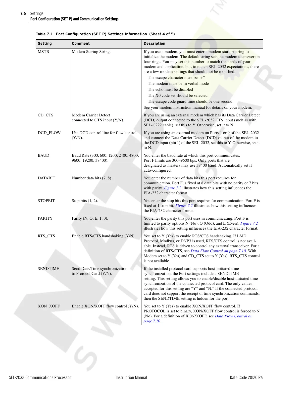
7.6
SEL-2032 Communications Processor Instruction Manual Date Code 20120126
Settings
Port Configuration (SET P) and Communication Settings
MSTR Modem Startup String. If you use a modem, you must enter a modem startup string to
initialize the modem. The default string sets the modem to answer on
four rings. You may set this number to match the needs of your
modem and application, but, to match SEL-2032 expectations, there
are a few modem settings that should not be modified:
The escape character must be “+”
The modem must be in verbal mode
The echo must be disabled
The X0 code set should be selected
The escape code guard time should be one second
See your modem instruction manual for details on your modem.
CD_CTS Modem Carrier Detect
connected to CTS input (Y/N).
If you are using an external modem which has its Data Carrier Detect
(DCD) output connected to the SEL-2032 CTS input (such as with
SEL-C222 cable), set this to Y. Otherwise, set it to N.
DCD_FLOW Use DCD control line for flow control
(Y/N).
If you are using an external modem on Ports 1 or 9 of the SEL-2032
and connect the Data Carrier Detect (DCD) output of the modem to
the DCD input (pin 1) of the SEL-2032, set this to Y. Otherwise, set it
to N.
BAUD Baud Rate (300; 600; 1200; 2400; 4800;
9600; 19200; 38400).
You enter the baud rate at which this port communicates.
Port F limits are 300–9600 bps. Only ports that are
designated as masters may use 38400 baud. Automatically set if
auto-configured.
DATABIT Number data bits (7, 8). You enter the number of data bits this port requires for
communication. Port F is fixed at 8 data bits with no parity or 7 bits
with parity. Figure 7.2 illustrates how this setting influences the
EIA-232 character format.
STOPBIT Stop bits (1, 2). You enter the stop bits this port requires for communication. Port F is
fixed at 1 stop bit. Figure 7.2 illustrates how this setting influences
the EIA-232 character format.
PARITY Parity (N, O, E, 1, 0). You enter the parity this port uses in communicating. Port F is
limited to parity options N (No), O (Odd), and E (Even). Figure 7.2
illustrates how this setting influences the EIA-232 character format.
RTS_CTS Enable RTS/CTS handshaking (Y/N). You set to Y (Yes) to enable RTS/CTS handshaking. If LMD
Protocol, Modbus, or DNP3 is used, RTS/CTS control is not avail-
able. Instead, RTS is driven to control any external transceiver. For a
definition of RTS/CTS, see Data Flow Control on page 7.10. With
Modem set to Y (Yes) and CD_CTS set to Y (Yes), RTS_CTS control
is not available.
SENDTIME Send Date/Time synchronization
to Protocol Card (Y/N).
If the installed protocol card supports host-initiated time
synchronization, the Port settings include a SENDTIME
setting. This setting allows you to enable/disable host-initiated time
synchronization of the connected protocol card. The only values
accepted for this setting are “Y” and “N.” If the connected protocol
card does not support the receipt of time synchronization commands,
then the SENDTIME setting is hidden for the port.
XON_XOFF Enable XON/XOFF flow control (Y/N). You set to Y (Yes) to enable XON/XOFF flow control. If
PROTOCOL is set to binary, XON/XOFF flow control is forced to N
(No). For a definition of XON/XOFF, see Data Flow Control on
page 7.10.
Table 7.1 Port Configuration (SET P) Settings Information (Sheet 4 of 5)
Setting Comment Description
Courtesy of NationalSwitchgear.com