217
33) ALTERNATOR (40 amp version) (No. 185046320)
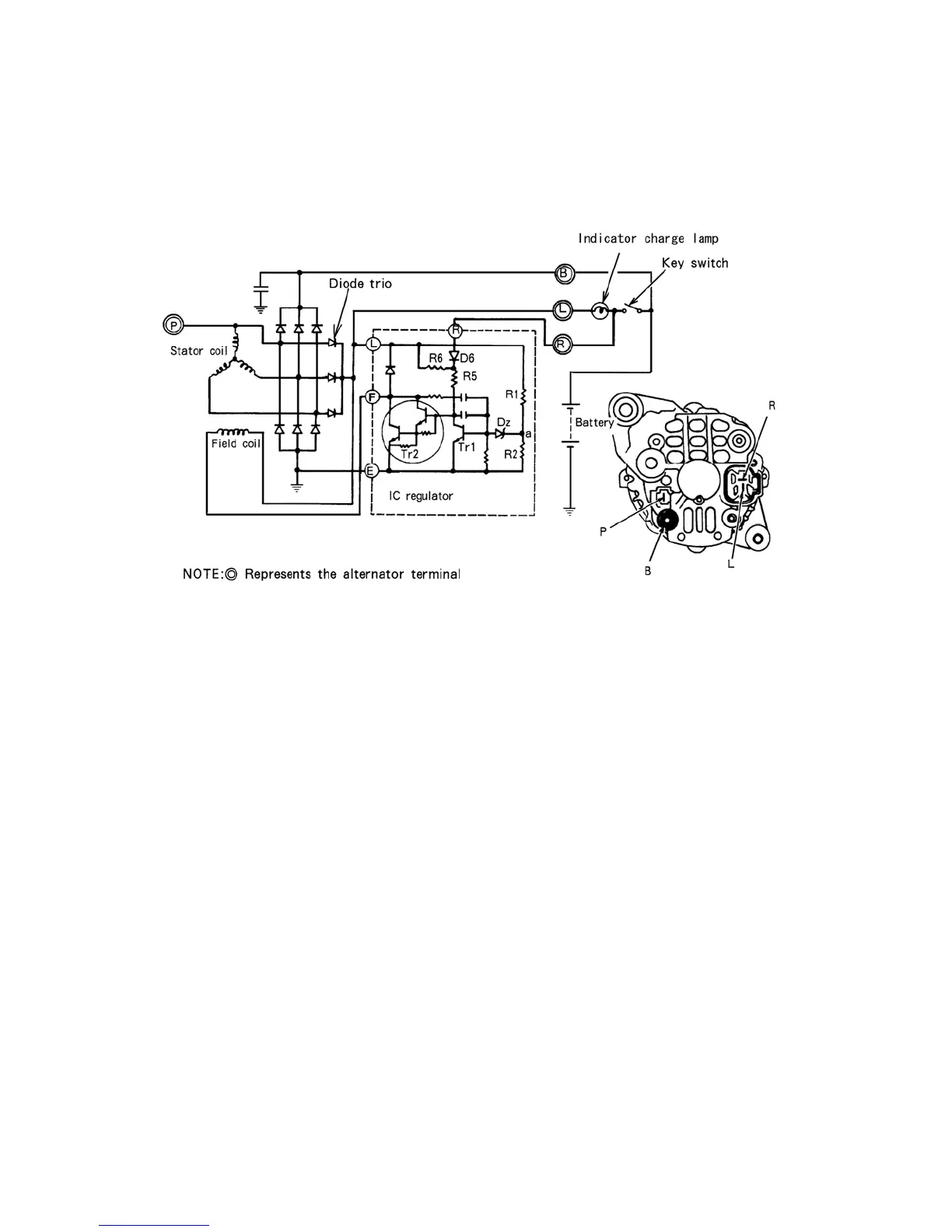
1. Charging circuit
595Y
2. Description
A. The charging circuit and internal connection are shown in Fig. 595Y. The charging system
consists of an I C regulator built in alternator, a battery and connecting wires. Because of
the use of IC, the voltage regulator is very compact and is built into the alternator.
B. The field current flows directly from the diode trio to the field coil with out passing
through the external circuit. But to help the initial voltage built up when the engine is
started, the field current is supplied through the indicator lamp from the battery.
C. Since the frequency pulse output of 1/10 the alternator speed develops on P terminal, this
terminal is used for speed detection.
 Loading...