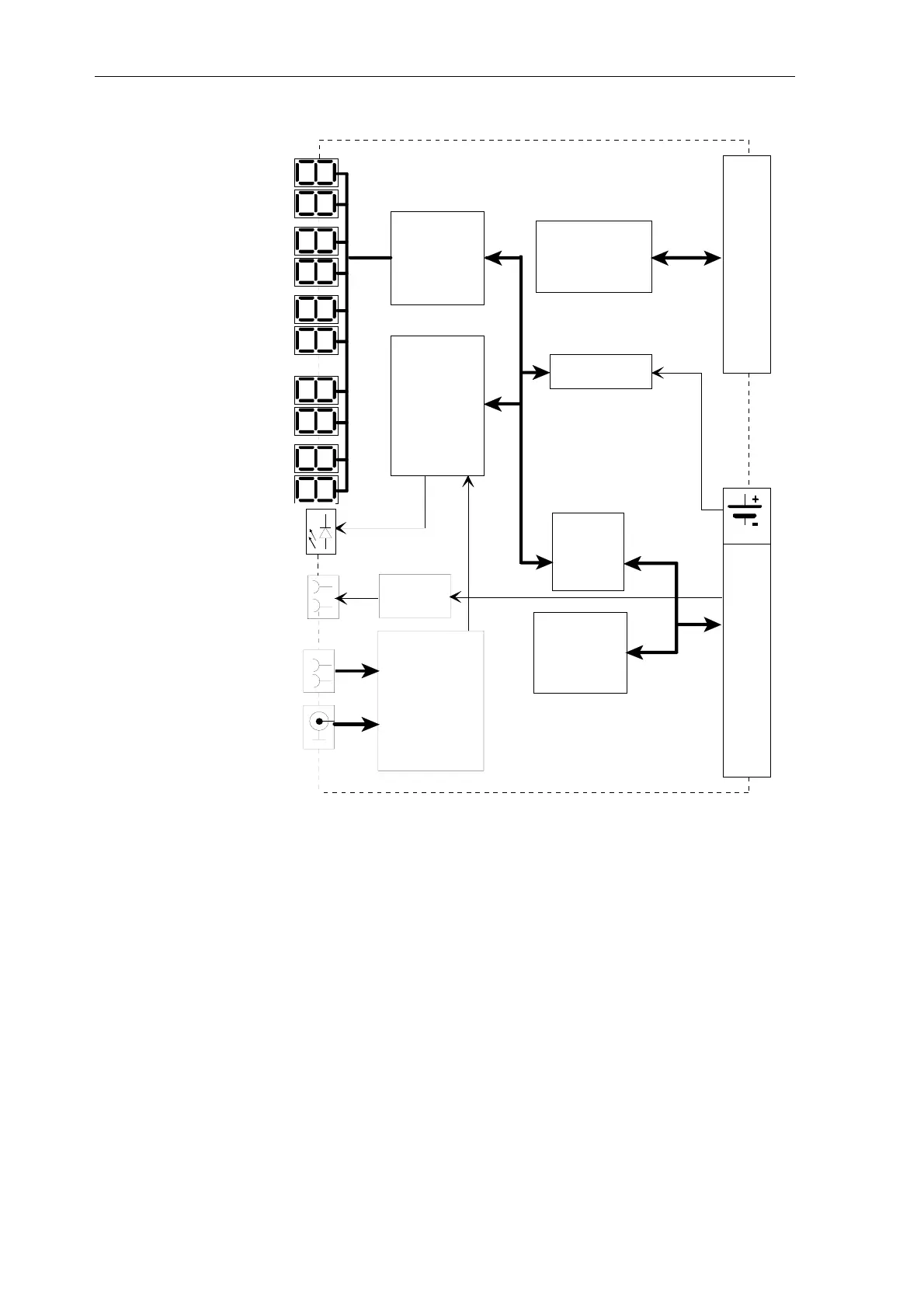
Coupling memory module
4-4 Hardware - SIMADYN D
Edition 03.2001
Communi-
cations
buffer L bus
32K X 16
80C186
dual-port
RAM
2K X 8
32K X 16
RDYIN-
relay
Input
Output
Status-
anzeige
Data- control- and address bus
Time
CPU
7-segment
LED control
Coupling memory
module C bus
Clock module
DCF77 receiver
and
IRIG-B converter
L bus
C bus
RDYIN
IRIG-B
Fig. 4-1 MM3 block diagram
Note: Led H1 (seconds) is located at the top, H10 (days) at the bottom!
The time is synchronized (time of day setting) via antenna using the DCF-77
radio signal. This signal can be received in Central Europe.
A differentiation is made between the following antennas:
• antenna for inside installation
• antenna for outside installation
The antenna must be aligned so that optimum reception is guaranteed.
Generally, this is towards Frankfurt/Main, where the signal transmitter is
located. The BNC socket X7 at the front panel is used to connect the
antenna.
Radio clock
DCF-77

 Loading...


