Cabinet Configuration and EMC Booksize
7.4 Arrangement of components and devices
Equipment Manuel for Booksize Power Modules
Manual, (GH2), Edition 06.2005, 6SL3097-2AC00-0BP2
7-15
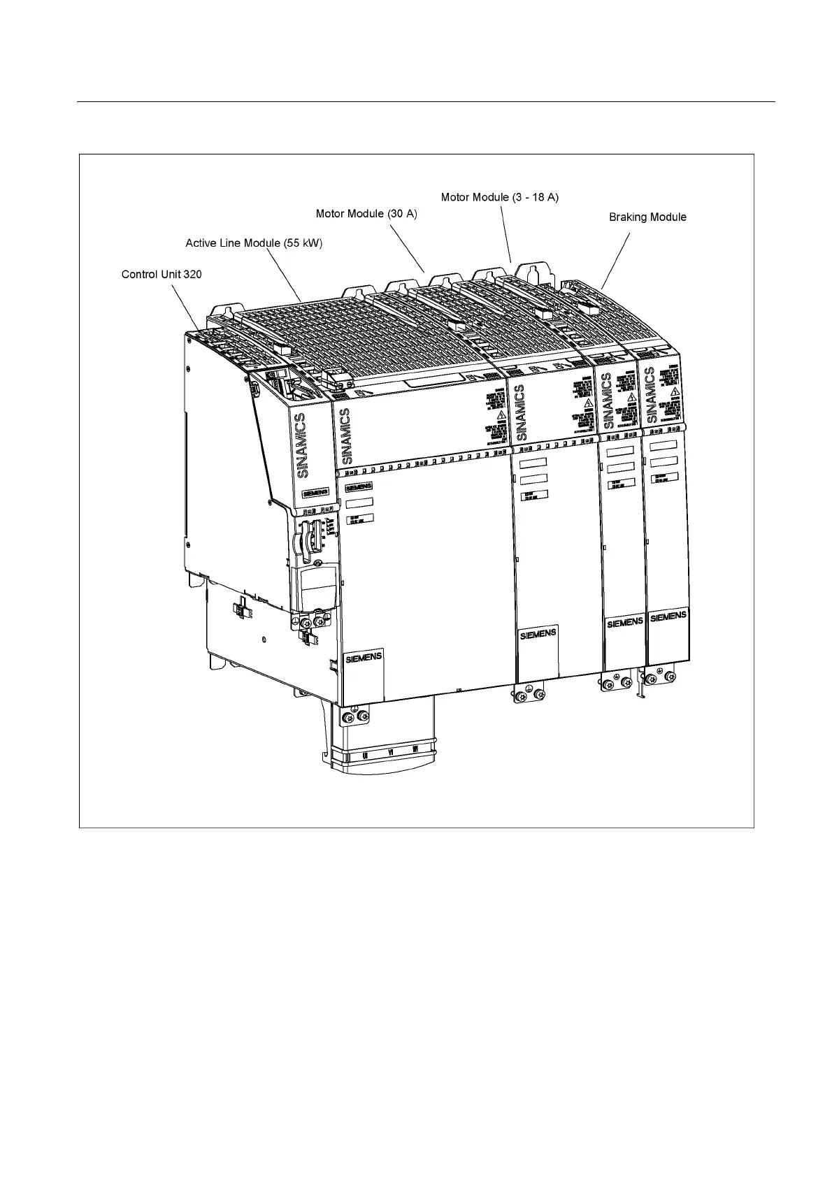
Figure 7-3 Example of a drive line-up
The components of the drive line-up should preferably be installed on a conductive mounting
surface to ensure low impedance between the component and the mounting surface.
Mounting plates with a galvanized surface are suitable.
The components can be arranged in one or more tiers. In a multiple-tier arrangement,
vertical installation or, in a cabinet row, side-by-side installation in different cabinet sections
is possible.
To determine the cross-section, use the DC link busbar current carrying capacity given in the
relevant technical specifications.
A distance of at least 150 mm is recommended between the line filter and the line reactor.

 Loading...


