Cabinet Configuration and EMC Booksize
7.4 Arrangement of components and devices
Equipment Manuel for Booksize Power Modules
Manual, (GH2), Edition 06.2005, 6SL3097-2AC00-0BP2
7-19
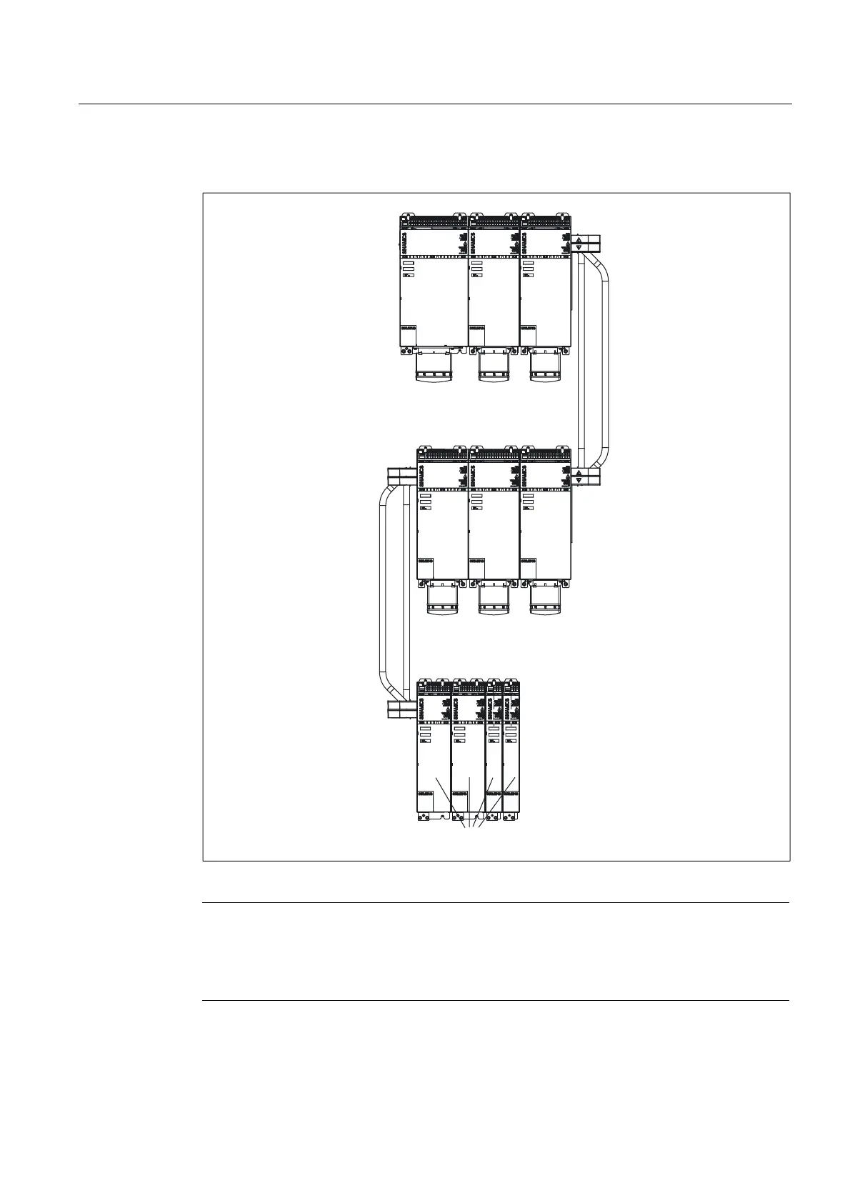
Multiple-tier configuration
$FWLYH
/LQH
0RGXOH
0RWRU
0RGXOH
0RWRU
0RGXOH
0RWRU
0RGXOH
0RWRU
0RGXOH
0RWRU
0RGXOH
0RWRU
0RGXOHV
'&OLQN
DGDSWHU
'&OLQN
DGDSWHU
Figure 7-6 Example of a three-tier configuration with modules between 50 and 200 mm wide
Note
When the power supply input is on the right-hand side of the drive line-up (e.g. in a multiple-
tier configuration), the above rules apply in reverse. This means that the Motor Modules are
arranged in order of power from the highest power to the lowest power followed by the DC
link components, such as the Braking Module.
In the case of Active Line Modules as of 55 kW, the Motor Modules can be mounted on the
right or left (see "DC link adapter").

 Loading...


