Appendix
A.3 Supported sample topologies
Drive functions
1046 Function Manual, 11/2017, 6SL3097-4AB00-0BP5
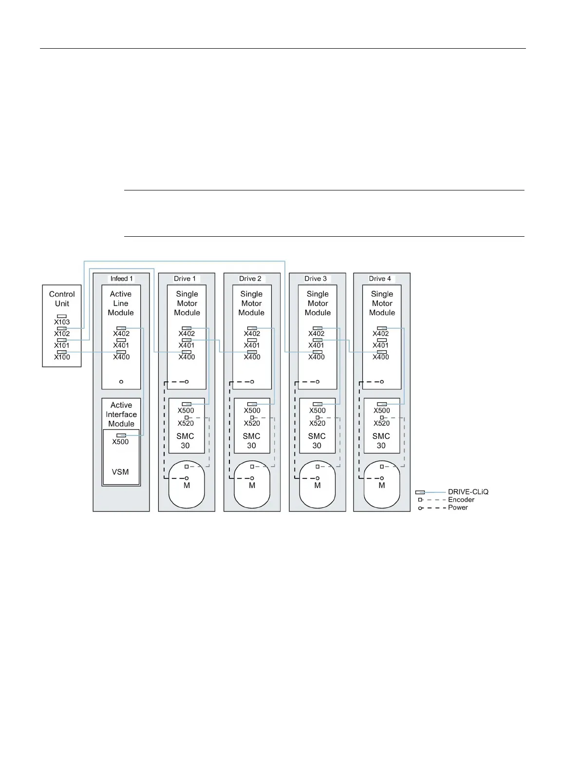
Drive line-up comprising four Motor Modules in the chassis format with different pulse frequencies
It is advantageous to connect Motor Modules with different pulse frequencies to different
DRIVE-CLiQ sockets of the Control Unit. They may also be connected at the same DRIVE-
CLiQ line.
In the following diagram, two Motor Modules (400 V, output ≤ 250 kW, pulse frequency
2 kHz) are connected to interface X101 and two Motor Modules (400 V, output > 250 kW,
pulse frequency 1.25 kHz) are connected to interface X102.
Note
The offline topology automatically generated in the STARTER commissioning tool must be
manually modified, if this topology wa
s wired.
Figure A-2 Drive line-up in chassis format with different pulse frequencies
 Loading...


