Basic information about the drive system
13.4 BICO technology: Interconnecting signals
Drive functions
Function Manual, 11/2017, 6SL3097-4AB00-0BP5
951
Connectors, CI: Connector Input, CO: Connector Output
A connector is a digital signal, e.g. in 32-bit format. It can be used to emulate words (16 bits),
double words (32 bits) or analog signals. Connectors are subdivided into connector inputs
(signal sink) and connector outputs (signal source).
Table 13- 3 Connectors
CI
Connector input
(signal sink)
Can be interconnected to a connector output as
source.
The number of the connector output must be
entered as a parameter value.
CO
Connector output
Can be used as a source for a connector input.
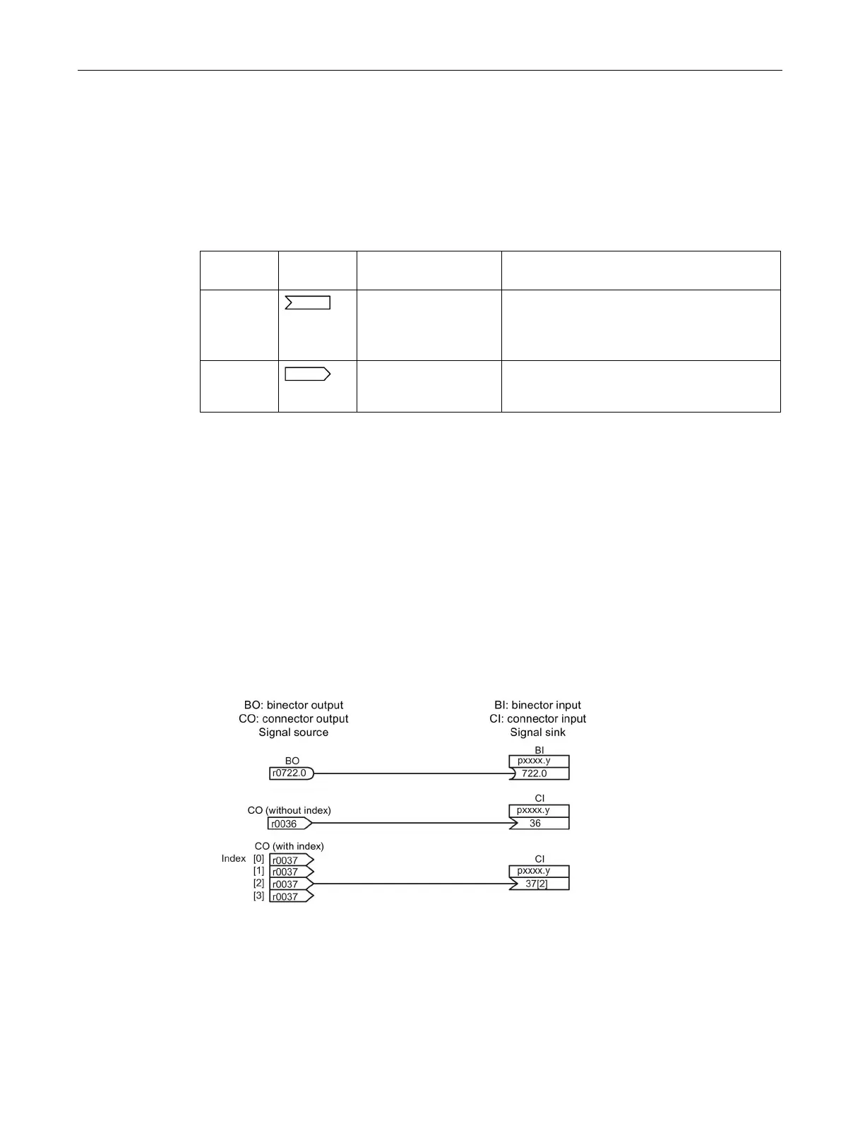
Interconnecting signals using BICO technology
To interconnect two signals, a BICO input parameter (signal sink) must be assigned to the
desired BICO output parameter (signal source).
The following information is required in order to connect a binector/connector input to a
binector/connector output:
● Binectors: Parameter number, bit number, and drive object ID
● Connectors with no index: Parameter number and drive object ID
● Connectors with index: Parameter number, index, and drive object ID
● Data type (signal source for connector output parameter)
Figure 13-10 Interconnecting signals using BICO technology
 Loading...


