Basic functions
7.13 Motor Module as a Braking Module
Drive functions
Function Manual, 11/2017, 6SL3097-4AB00-0BP5
351
Configuring resistors
Rules and values
● Under no circumstances may the resistance values for the peak braking power, which are
listed in this table, be fallen below!
● The resistance values apply for each of the three resistors in a star connection in the cold
state.
● Each braking resistor absorbs 1/3 of the total braking power. It is imperative that you take
into account the power rating of the resistors.
● For a delta connection, multiply the braking resistance value by a factor of 3.
● The tables apply for all Motor Modules of the "chassis" format (liquid or air cooling).
● The cable lengths to the resistors must be at least 10 m.
● At rated voltages of 380 V to 480 V, Motor Modules with a type rating ≥ 250 kW are
permitted.
● At rated voltages of 500 V to 690 V, all Motor Modules in the "chassis" format have been
released for use of this function.
You can enter the resistance value in a star connection into parameter p1360. The default
setting of the resistance values is calculated from:
● p1360 = p1362[0] / (√(6) · r0207[0])
● p1362[0] = Braking Module activation threshold according to the following table.
● r0207[0...4] = rated current of the Motor Module
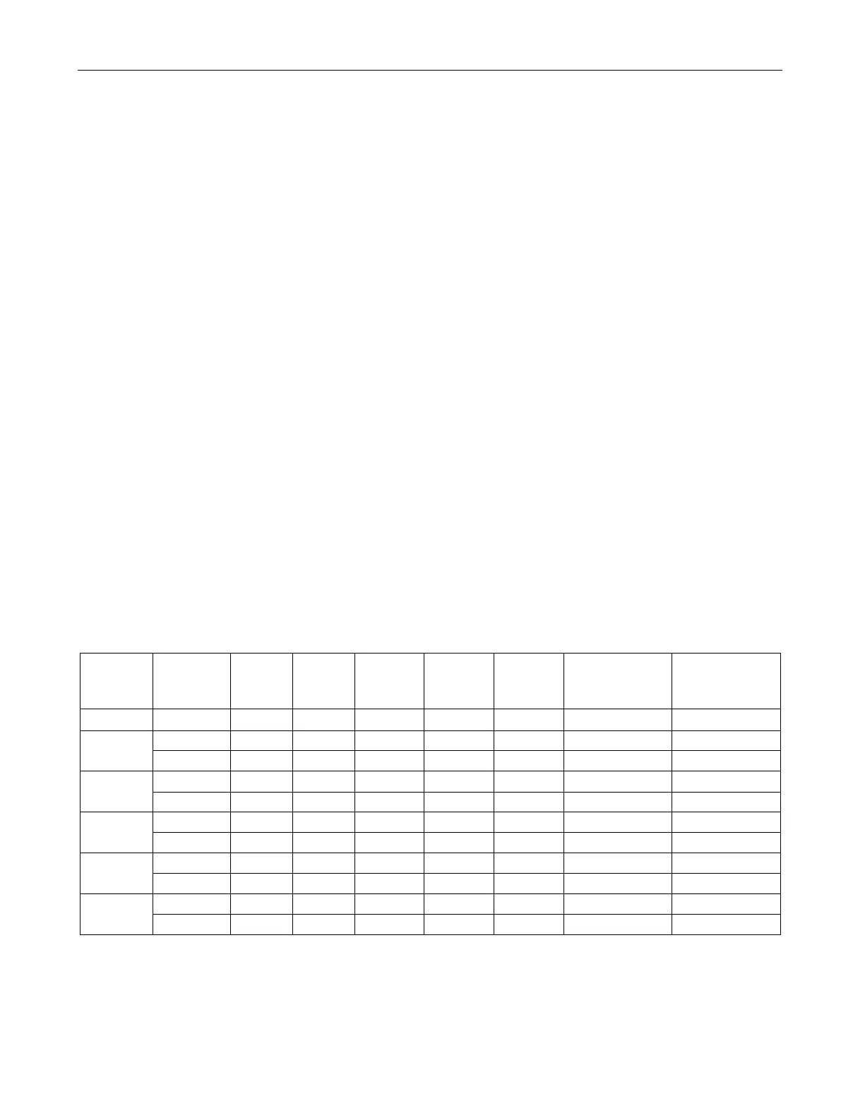
Table 7- 8 Resistance table 380 - 480 V supply voltage
U
DC link
chopper
threshold
Continu-
ous brak-
ing power
Resistance at the
continuous brak-
ing power
Resistance at the
peak braking
power
G
H 400 605 545 667 445 668 0.500 0.333
H
H
J
 Loading...


