Appendix
A.3 Supported sample topologies
Drive functions
Function Manual, 11/2017, 6SL3097-4AB00-0BP5
1047
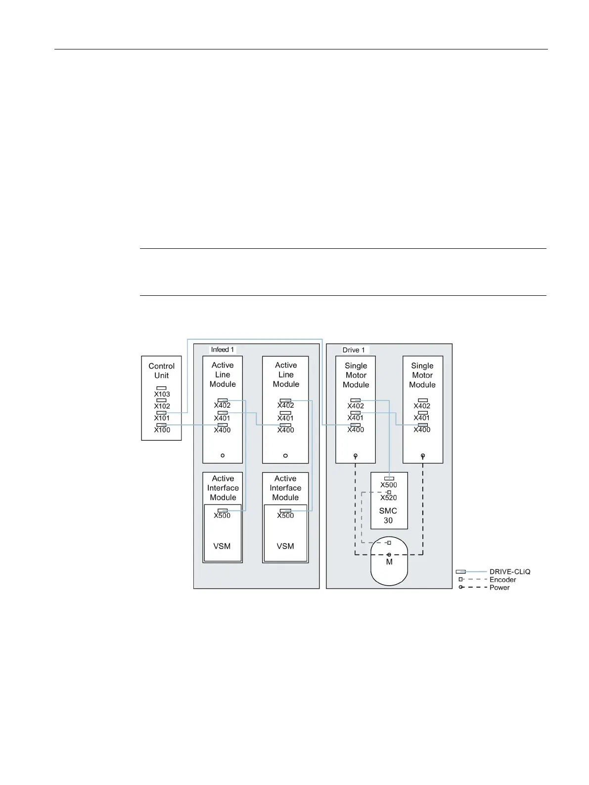
Topology example: Parallel Motor Modules in vector control
Drive line-up with 2 Line Modules and Motor Modules connected in parallel - in the chassis format of
the same type
Parallel-connected Line Modules in the chassis format and Motor Modules in the chassis
format of the same type can be connected to a DRIVE-CLiQ socket of the Control Unit.
In the following diagram, two Active Line Modules and two Motor Modules are connected to
the X100 or X101 socket.
You can find additional notes in Chapter "Parallel connection of power units" in the
SINAMICS S120 Function Manual.
Note
The offline topology automatically generated in the STARTER commissioning tool must be
manually modified, if this topology was wired.
Figure A-3 Drive line-up with parallel-connected power units in the chassis format
 Loading...


