Servo control
4.11 Optimizing the current and speed controller
Drive functions
142 Function Manual, 11/2017, 6SL3097-4AB00-0BP5
Example of measuring the speed controller frequency response
By measuring the speed controller frequency response and the control system, critical
resonance frequencies can, if necessary, be determined at the stability limit of the speed
control loop and dampened using one or more current setpoint filters. This normally enables
the proportional gain to be increased (e.g. K
p_n
= 3 default value).
After the K
p_n
value has been set, the ideal integral time T
n_n
(e.g. reduced from 10 ms to
5 ms) can be determined.
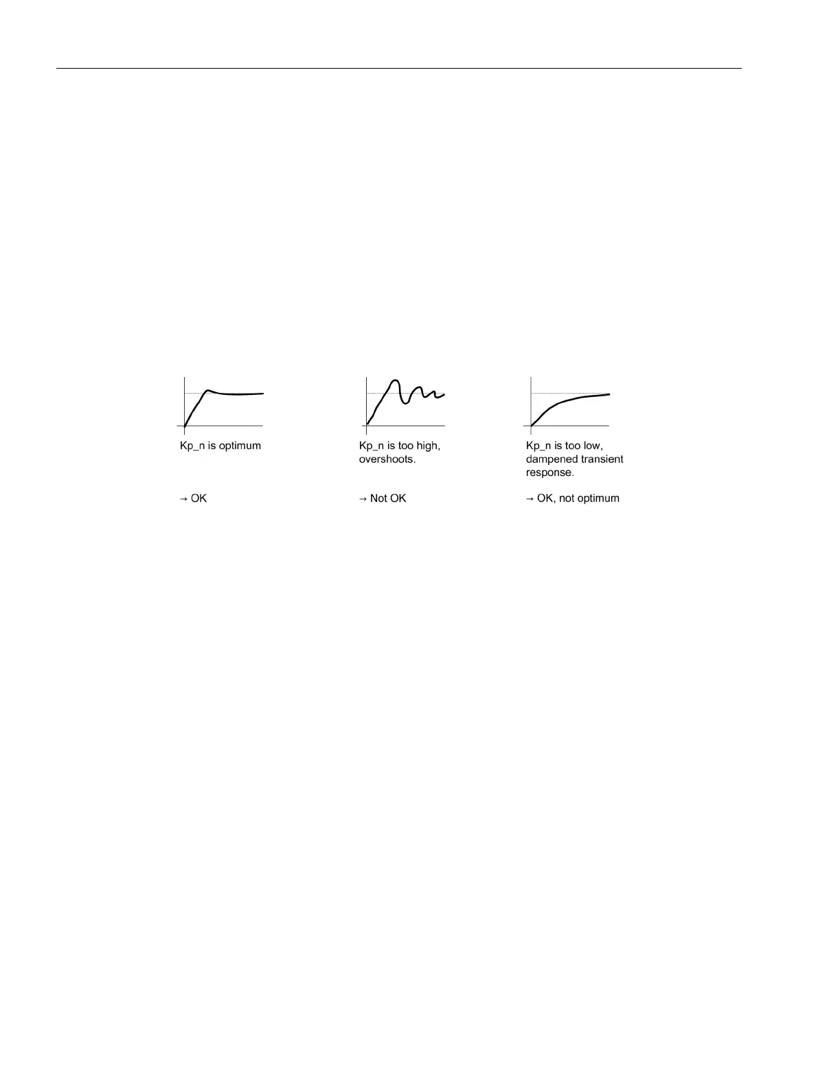
Example of speed setpoint step change
A rectangular step change can be applied to the speed setpoint via the speed setpoint step
change measuring function. The measuring function has preselected the measurement for
the speed setpoint and the torque-generating current.
Figure 4-15 Setting the proportional gain K
p
 Loading...


