Communication
11.4 Communication via MODBUS TCP
Drive functions
Function Manual, 11/2017, 6SL3097-4AB00-0BP5
865
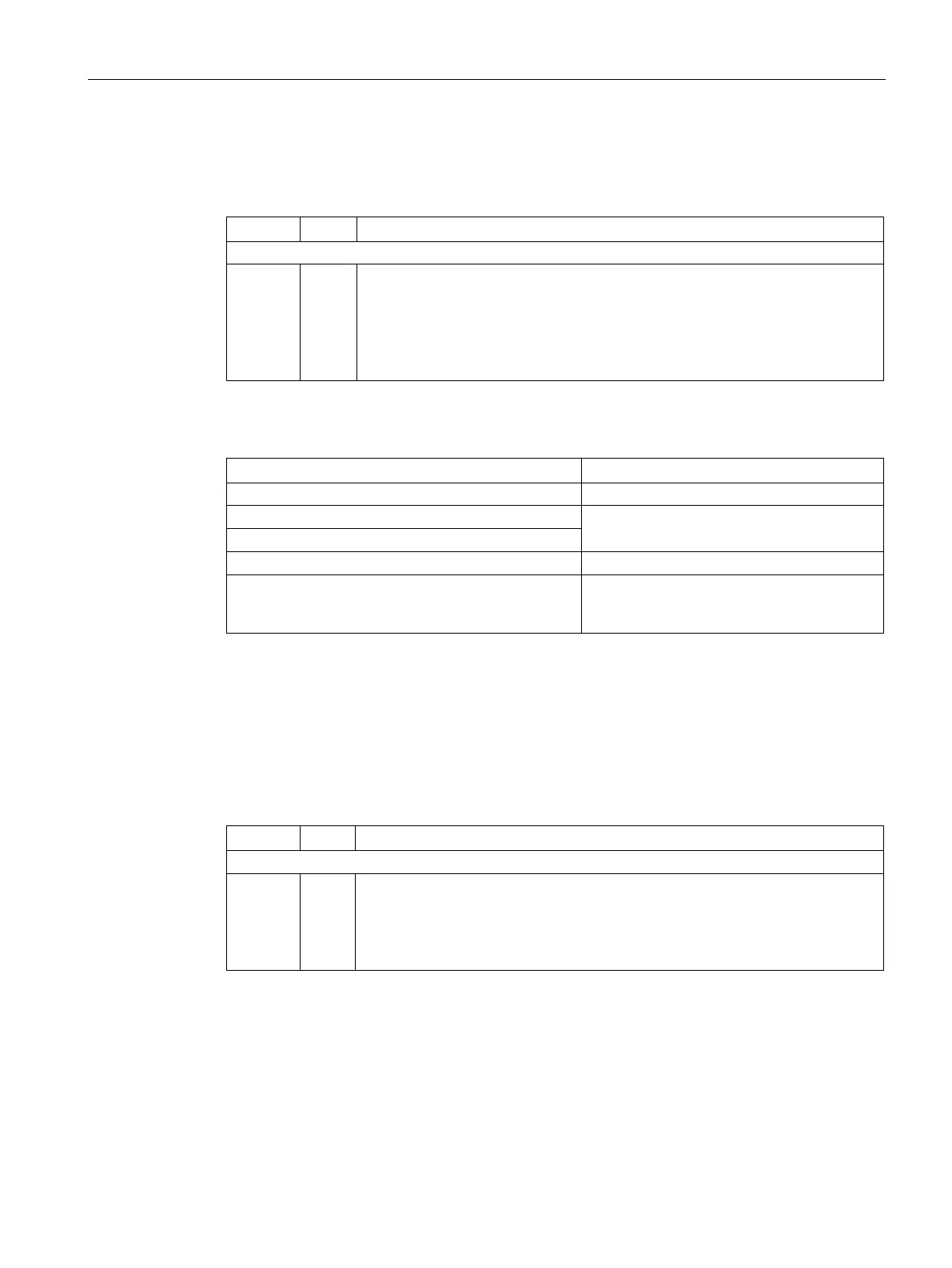
The response returns the corresponding data set:
Table 11- 23 Device response to the read request, example
04 h
11 h
22 h
33 h
8
9
10
11
Number of bytes (4 bytes are returned)
Data first register "High"
Data first register "Low"
Data second register "High"
Data second register "Low"
Table 11- 24 Invalid read request
Exception code 02 (invalid data address)
Read a write-only register
Telegram in which all values are set to 0.
Controller addresses more than 125 registers
Exception code 03 (invalid data value)
The start address and the number of registers of an
address are located outside of a defined register
Exception code 02 (invalid data address)
Structure of a write request via Modbus function code 06 (FC 06)
Start address is the holding register address.
Via FC 06, with one request, only precisely one register can be addressed. The value, which
is written to the addressed register, is contained in bytes 10 and 11 of the write request.
Table 11- 25 Structure of a write request for device number 17, example
00 h
63 h
55 h
8
9
10
Register start address "High" (write register 40100)
Register start address "Low"
Register data "High"
 Loading...


