Applications
12.5 Motor changeover
Drive functions
922 Function Manual, 11/2017, 6SL3097-4AB00-0BP5
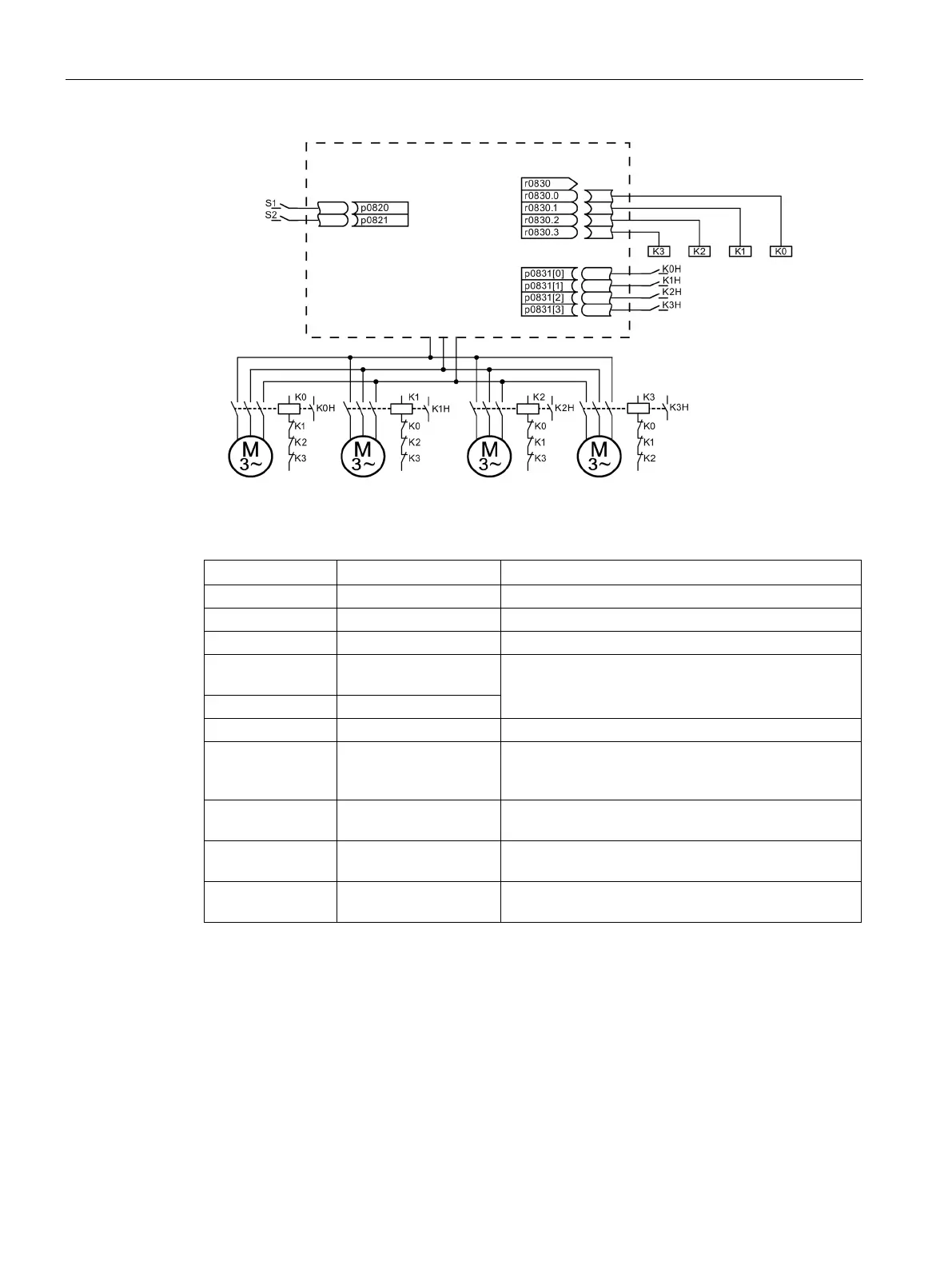
Figure 12-6 Example of motor changeover
Table 12- 1 Settings for the example
p0180 4 Configure four DDS.
The MDS are assigned to the DDS.
p0820, p0821 Digital inputs DDS
The digital inputs for motor changeover via DDS selec-
tion are selected. Binary coding is used (p0820 = bit 0,
etc.).
Different numbers indicate a different thermal model.
p0827[0...3] 0, 1, 2, 3 Assigning the bit from r0830 to the MDS. If p0827[0] =
1, for example, bit p0830.1 is set when MDS0 is se-
r0830.0 to r0830.3 Digital outputs, contac-
The digital outputs for the contactors are assigned to
p0831[0...3] Digital inputs, auxiliary
The digital inputs for the feedback signal of the motor
p0833.0..2 0, 0, 0 The drive controls the contactor circuit and pulse inhi-
bition. Parking bit (Gn_ZSW14) is set.
Procedure for changeover between motor data sets
1. Start condition:
For synchronous motors, the actual speed must be lower than the speed at the start of
field weakening. This prevents the regenerative voltage from exceeding the terminal
voltage.
2. Pulse inhibit:
The pulses are inhibited after a new drive data set is selected with p0820 to p0824.
 Loading...


