130
394149/C
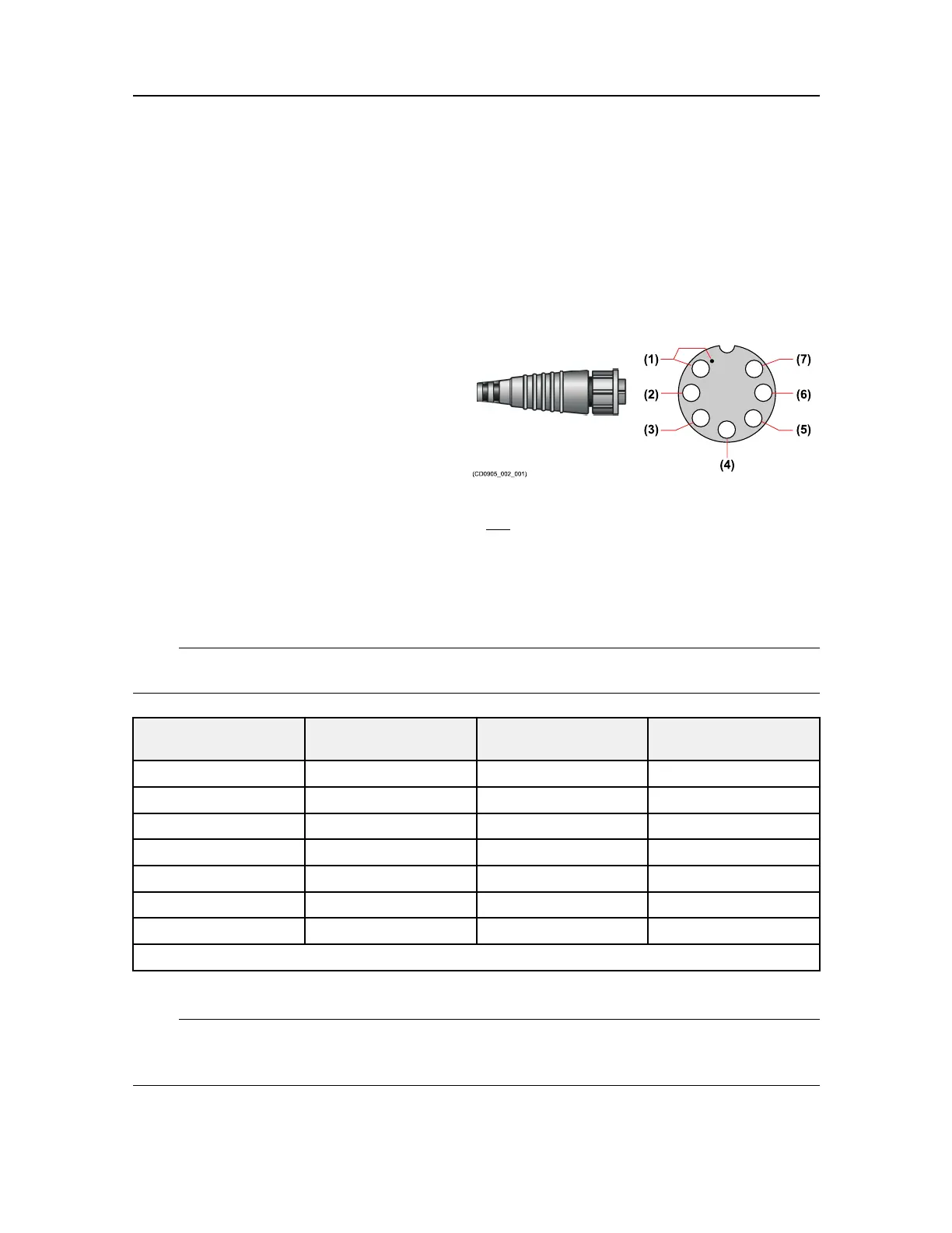
BOptionaljunctionboxwithamale7–pinsocket
CCircular12-pinAmphenoltransducersocket
DThelowfrequencyelementisconnectedtosocketsCandD
EThehighfrequencyelementisconnectedtosocketsHandJ
FThermistoroutput
(1)
(2)
(3)
(6)
(7)
(4)
(5)
(CD0905_002_001)
Thecablescreenmustbeconnectedto
thehousingonthetransducerplugand
toterminalN.
Ifyouneedtosplicethetransducer
cable,westronglyrecommendtheuse
ofametaljunctionboxwithproper
cableglands.Thecablescreenmust
beconnectedtothecableglands.The
cablescreenandthejunctionboxchassismustnotbeconnectedtovesselground.Avoid
groundloops.Y oumustusethesametypeofcableastheoriginaltransducercable,contact
KongsbergMaritimeforadvice.
Westronglyrecommendthatyouinstallthetransducercableinasteelconduit.
Note
Thetransducercablemustnotbeexposedtooilorotherpetroleumuids!
Pinon
transducerplug
SignalWire
colour
Pinon
transducersocket
1
HighfrequencyRed
H
2
HighfrequencyBlack
J
3
LowfrequencyBlue
C
4Screen
Housing
5
LowfrequencyWhite
D
6
Thermistor
Green
N/A
7
ThermistorY ellowN/A
Pins6and7onthetransducerareconnectedtothethermistorthathasbeenbuiltintothetransducerbody.
Note
NeithertheEK80softwarenortheWideBandTransceiver(WBT)supportinputfroma
temperaturesensor.
SimradEK80