Section04ENGINE
Subsection 02 (ENGINE LEAK TEST AND DIMENSION MEASUREMENT)
Engine
Check the following:
– All jointed surfaces and screw/stud threads of
engine:
• spark plug base, insulator
• cylinder head
• RAVE valve bellows, piston and housing
• cylinder crankcase halves (joint)
• oil injection pump mounting flange (O-ring)
• coolant pump housing
• bleed screws/plugs
• crankcase grease reservoir fitting.
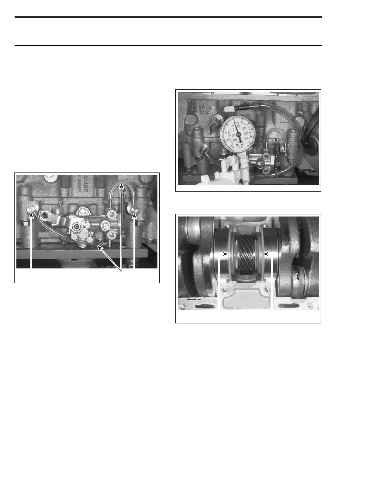
– Small injection oil lines coming from pump.
A32C1GA
1
2
1
TYPICAL
1. Injection nipples
2. Small injection oil lines
Check for air bubbles or oil column going toward
pump. It indicates defective check valve in injec-
tion nipples.
– Remove cooling system cap.
Check for air bubbles in antifreeze. It indicates de-
fective cylinder head O-ring or cylinder base gas-
ket.
– Remove drive pulley then check crankshaft
outer seal.
– Remove rewind starter and magneto system
then check crankshaft outer seal.
– Check pump shaft gear oil reservoir.
Pump Shaft Oil Gear Reservoir
Install air pump on adapter and pressurize as
above.
A32C1HA
If pressure drops, it indicates a defective crank-
shaft inner seal.
2
A32C1IA
1
TYPICAL — CRANKSHAFT INSTALLED IN UPPER
HALF CRANKCASE
1. Crankshaft inner seal on PTO side
2. Crankshaft inner seal on MAG side
112 mmr2004-Rev

 Loading...
