Section 09 STEERING/FRONT SUSPENSION
Subsection 02 (FRONT SUSPENSION)
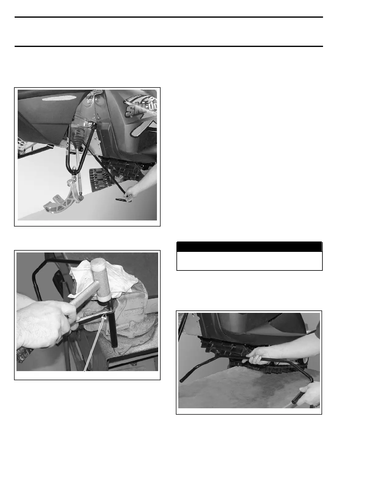
Lift front of vehicle enough so that stabilizer bar
no. 7 can be rotated downward to allow to slide it
out.
A33F24A
To remove bushing no. 25,usea13mm(1/2in)
open wrench and tap bushing out as shown.
1
A33F25A
1. Use a 13 mm (1/2 in) open wrench to push bushing out
INSPECTION
Check all plastic bushings for wear. Replace as
required.
Check condition of ski leg no. 12. Replace as re-
quired.
Check for straightness of lower and upper arms.
Replace as required.
Check condition of ball joints. Replace as re-
quired.
Check skis and runners no. 5 for wear, replace as
necessary.
Check condition of ski stopper no. 26.Replaceit
when deteriorated.
To check condition of shock absorber, refer to
SUSPENSION then look for SHOCK ABSORBER
INSPECTION.
INSTALLATION
For assembly, reverse the disassembly procedure.
However, pay attention to the following.
Tighten nuts and screws to proper torque as men-
tioned in exploded view.
Nuts with a cotter pin: After applying the proper
torque, continue tightening as necessary to allow
cotter pin insertion. Ensure to properly secure
cotter pin.
WARNING
Always install new cotter pins at assembly
and properly bend their ends.
Stabilizer Bar
Ensure to properly position stabilizer bar before
insertion in frame.
A33F26A
Install the stabilizer bar bushing no. 23 making
sure to place its tab over the access hole located
on the LH side.
338 mmr2004-Rev

 Loading...
