Section052–TEC ENGINE MANAGEMENT
Subsection 02 (COMPONENT INSPECTION AND ADJUSTMENT)
Unscrew all retaining screws and remove the en-
gine ECM from its support.
Install the new ECM to the support.
Reconnect ECM connectors to ECM, and then bat-
tery cables.
Transfer the data from the previous ECM to the
new one using B.U.D.S. then proceed with the
required resets and reprogram tether cord cap(s),
ifyouwereunabletotransferthedata.
NOTE: If data cannot be transferred, manually en-
ter information in Vehicle tab.
After performing the required resets, ensure to
clear all faults from the newly replaced ECM.
Start the engine and increase engine speed above
5000RPMtobesurenofaultappears.
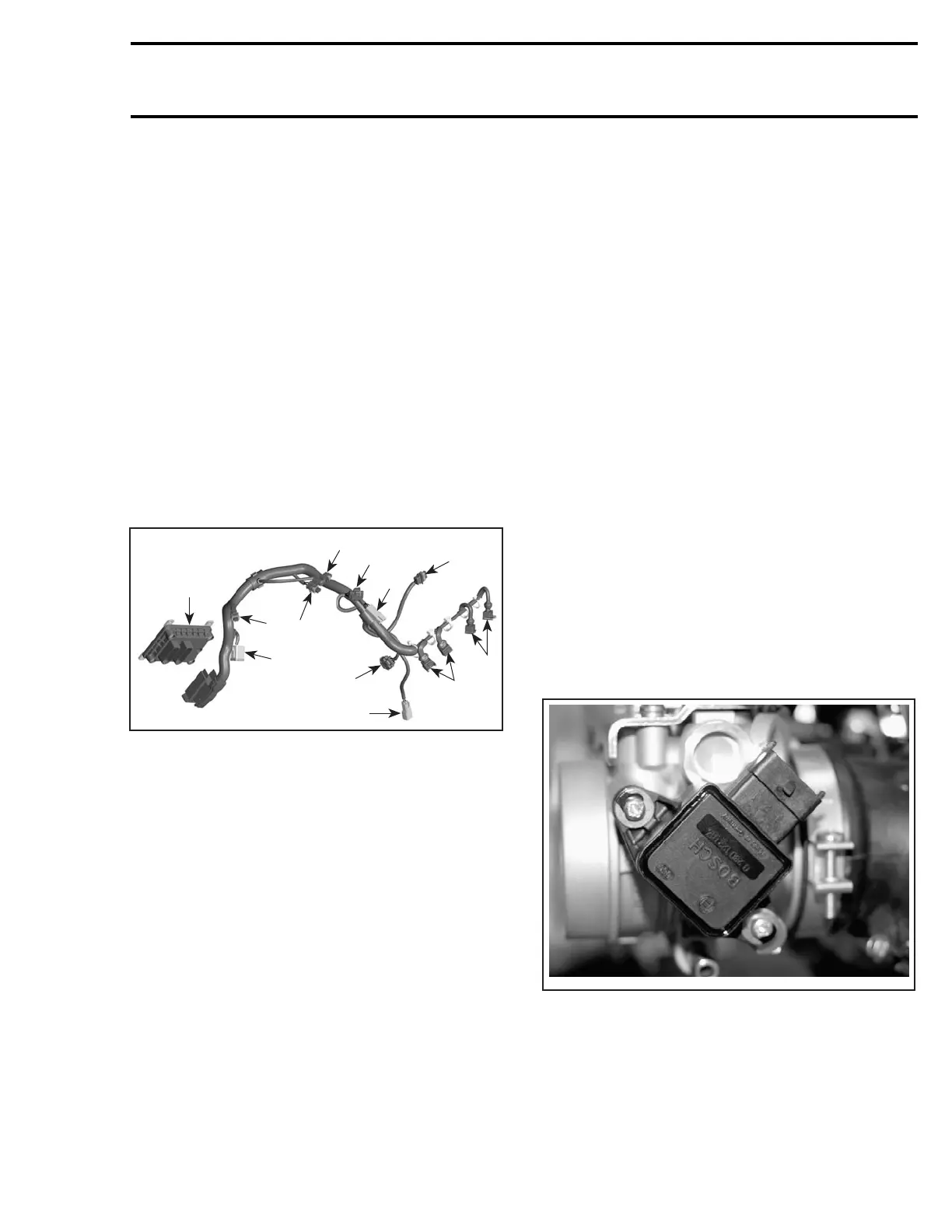
ENGINE WIRING HARNESS
1
A32CCQA
3
9
8
10
2
5
11
7
12
6
4
1. ECM
2. CTS connector
3. EGTS connector
4. Fuel injector connector (cylinder MAG side)
5. Ignition coil connector
6. Fuel injector connector (cylinder PTO side)
7. TPS connector
8. ATS connector
9. Engine connector
10. APS connector
11.KS connector
12. CPS connector
NOTE: Check if wiring harness shows any signs
of scoring.
Resistance Test
Check continuity of the circuits according to the
wiring diagram in the WIRING DIAGRAMS section
of this manual.
If wiring harness is good, check the respective
sensor/actuator as described in this section.
Otherwise, repair the connectors, replace the
wiring harness or the ECM as diagnosed.
Removal
Remove air intake silencer.
Disconnect the wiring harness from all sensors/
actuators.
Disconnect the connector from the ECM.
Cut all locking tie which are holding the wiring har-
ness in position.
Remove complete wiring harness.
Installation
First connect the connector A to the ECM and the
engine connector to the vehicle wiring harness.
Reconnect the wiring harness to all sensors/actu-
ators and reinstall all locking tie that have been re-
moved.
Install all remaining parts, which have been re-
moved.
THROTTLE POSITION SENSOR
(TPS)
General
The throttle position sensor (TPS) is a potentiome-
ter that sends a signal to the ECM which is propor-
tional to the throttle shaft angle.
A32C9RA
THROTTLE POSITION SENSOR (TPS)
IMPORTANT: Prior to testing the TPS, ensure
that mechanical components/adjustments are
adequate according to THROTTLE BODY in AIR
INDUCTION SYSTEM above.
mmr2004-Rev 189

 Loading...
