Section 06 TRANSMISSION
Subsection 06 (CHAINCASE)
REMOVAL AND DISASSEMBLY
To remove chaincase proceed as follows.
Remove battery and battery rack (if so equipped)
to gain access, refer to BATTERY section.
Remove hair pin no. 8. Release drive chain ten-
sion by unscrewing tensioner adjustment screw.
Drain oil by removing drain plug no. 24.
3,4,5,6,13,16,17, Cotter Pin, Nut,
Sprocket, Shim and Drive Chain
Apply parking brake.
Remove cotter pin no. 3 and nut no. 4 retaining
upper sprocket no. 5 and screw no. 15 retaining
lower sprocket no. 16. Pull sprockets and drive
chain simultaneously. Remove shims no. 6 and
no. 17.
NOTE: Should countershaft removal be required,
refer to BRAKE then look for COUNTERSHAFT
REMOVAL.
Release parking brake.
Remove3nutsno. 14.
Unfold locking tab no. 23 then remove caliper re-
taining screws no. 22.
Release track tension, use drive axle holder no. 20
(P/N 529 007 200).
A32D0LA
2
529 007 200
1
TYPICAL
1. Drive axle
2. Suspension front arm upper axle
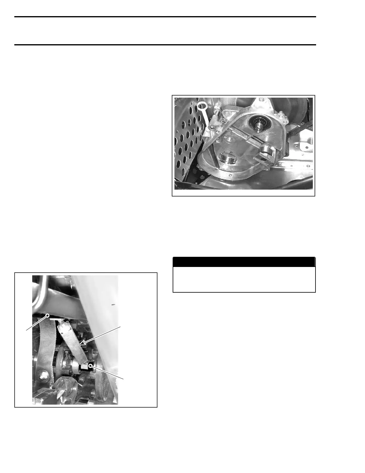
Pry out drive axle oil seal no. 19 from chaincase.
Pull chaincase from drive axle and countershaft.
Using 2 large prybars inserted between chaincase
housing no. 7 and frame, pry complete assembly
from vehicle.
A32D0KA
TYPICAL — CHAINCASE HOUSING REMOVAL
INSPECTION
Visually inspect the chain for cracked, damaged or
missing links. Check for worn or defective bear-
ings, sprockets and chain tensioner components.
WARNING
If chain deflection is greater than 38 mm
(1.5 in) (without chain tensioner), replace
chain and check condition of sprockets.
GEAR RATIO MODIFICATION
For particular applications, the number of teeth of
the sprockets can be increased or decreased on
lower and upper sprockets.
Refer to TECHNICAL DATA for gear ratios.
CAUTION: Gear ratio modifications should
only be performed by experienced mechanics
since they can greatly affect vehicle perfor-
mance.
NOTE: For high altitude regions, a service bulletin
will give information about calibration according to
altitude.
246 mmr2004-Rev

 Loading...
