Section 07 ELECTRICAL SYSTEM
Subsection 05 (TESTING PROCEDURE)
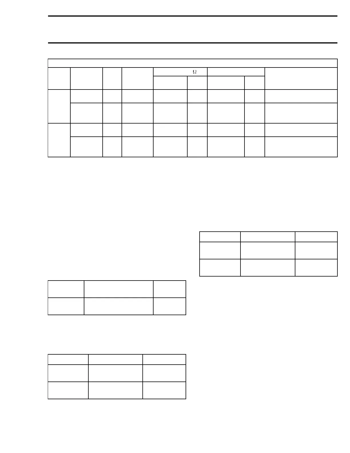
360 W MODEL (ignition and electrical system testing)
RESISTANCE VOLTAGE V
PART
TEST TO BE
PERFORMED
WIRE
COLOR
MULTIMETER
PROBE
CONNECTION
MULTIMETER
SCALE
VALUE
(ohms)
MULTIMETER
SCALE
VALUE
(volt)
NOTE
Coil
WH/GN
and BK
5–RC-85–F
5–RC-86–F
— — 00.0 Vdc
10.5 to
13.5
Engine idling (1500 to 1800 RPM)
Relay (with
battery)
Contacts
RD/WH
and
RD/BR
5–RC-87–F
5–RC-30–F
— — 00.0 Vdc
00.0 to
0.10
Engine idling (1500 to 1800 RPM)
Coil
WH/GN
and BK
5–RC-85–F
5–RC-86–F
— — 00.0 Vdc
10.5 to
13.6
Engine idling (1500 to 1800 RPM)
Relay
(without
battery)
Contacts
RD/BU
and
RD/BR
5–RC-87–F
5–RC-30–F
— — 00.0 Vdc
00.0 to
0.11
Engine idling (1500 to 1800 RPM)
NOTE: If voltage is present at the coil and contact, replace the relay.
An approved automotive spark plug tester is preferred for testing the secondary winding voltage.
All cranking tests are performed with the manual starter. Faster cranking speeds may produce higher
voltages.
Ignition and electric starter will not work if the Engine stop switches is in the kill position.
Charging system test should be performed if a no spark condition is encountered on this vehicle.
INSPECTION OF HEATING
ELEMENTS
NOTE: All measurements must be performed at
21°C(70°F).
Throttle Lever Heating Element
Current Measurement
HIGH
INTENSITY
BROWN wire
0.23 A
minimum
LOW
INTENSITY
BROWN /YELLOW wire
0.13 A
minimum
Handlebar Grip Heating Element
Resistance Measurement
All Models except SDI
INTENSITY WIRES OHMS
HIGH
BLACK and
ORANGE/VIOLET
13.7 to 16.7*
LOW
BLACK and
ORANGE
6.8to8.4*
SDI Models
INTENSITY WIRES OHMS
HIGH
BLACK and
ORANGE/VIOLET
17 to 23.5*
LOW
BLACK and
ORANGE
8.5 to 11.8*
*When measuring resistance at terminals the ac-
tual value will be half the measurement in table.
The reason for that is the elements are connected
in parallel. Therefore the total resistance is half
the resistance of one element.
mmr2004-Rev 283

 Loading...
