Section04ENGINE
Subsection 08 (FUEL TANK AND FUEL PUMP)
NOTE: The following instructions are not applica-
ble on SDI models. See COMPONENT INSPEC-
TION AND ADJUSTMENT concerning fuel pump
procedure on these models.
REMOVAL
Remove air intake silencer and carburetors.
NOTE: Do not disconnect cables from carbure-
tors.
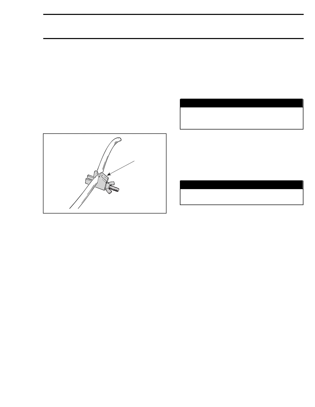
Install a hose pincher (P/N 295 000 076) on fuel
supplylineclosetopumpinlet.
A01B2JA
295 000 076
Disconnect fuel outlet line(s).
Disconnect impulse line.
Remove screws securing fuel pump to chassis.
PUMP VERIFICATION
Check fuel pump valves operation as follows:
Connect a clean plastic tubing to the inlet nipple
and alternately apply pressure and vacuum with
pump of leak test kit. The inlet valve should re-
lease with pressure and hold under vacuum.
Repeat the same procedure at the outlet nipple.
This time the outlet valve should hold with pres-
sure and also under vacuum.
NOTE: Plug remaining outlet with finger while
checking outlet valve.
Check impulse diaphragm and gasket on fuel
pump with twin outlets as follows:
Connect a clean plastic tubing to the impulse nip-
ple and plug vent hole on top cover on so equipped
models. Either apply pressure or vacuum. The di-
aphragm/gasket must not leak.
CLEANING AND INSPECTION
The entire pump should be cleaned with general
purpose solvent before disassembly.
Fuel pump components should be cleaned in gen-
eral purpose solvent and dried with compressed
air.
WARNING
Solvent with low flash point such as gasoline,
naphtha, benzol, etc, should not be used as
each is flammable and explosive.
Inspect diaphragm. The pumping area should be
free of holes, tears or imperfections. Replace as
needed.
INSTALLATION
Inverse removal procedure.
WARNING
Pressure test to ensure there is no leak in fuel
system.
mmr2004-Rev 163

 Loading...
