Section 06 TRANSMISSION
Subsection 03 (DRIVEN PULLEY)
DRIVEN PULLEY BUSHING WEAR LIMIT
mm (in)
Small bushing 38.30 (1.508)
Large bushing 108.2 (4.260)
Slider Shoe
Black slider shoe = forward.
Red slider shoe = reverse.
Check cam slider shoes no. 10 and no. 11 for
wear. Replace when inside edge thickness of cam
slider shoe slope base is worn to 1 mm (.039 in)
or less.
2
1
A15D0OA
3
1. Measure thickness of slope base here
2. Sliding pulley side
3. Slope base
BUSHING REPLACEMENT
Large Bushing
Remove Allen screws if applicable. Heat to break
Loctite bond.
Install support plate included in tool (P/N 529 031
100) inside sliding half.
Place extractor (P/N 529 035 575) below bushing.
A03D1WB
2
1
TYPICAL
1. Support plate
2. Extractor
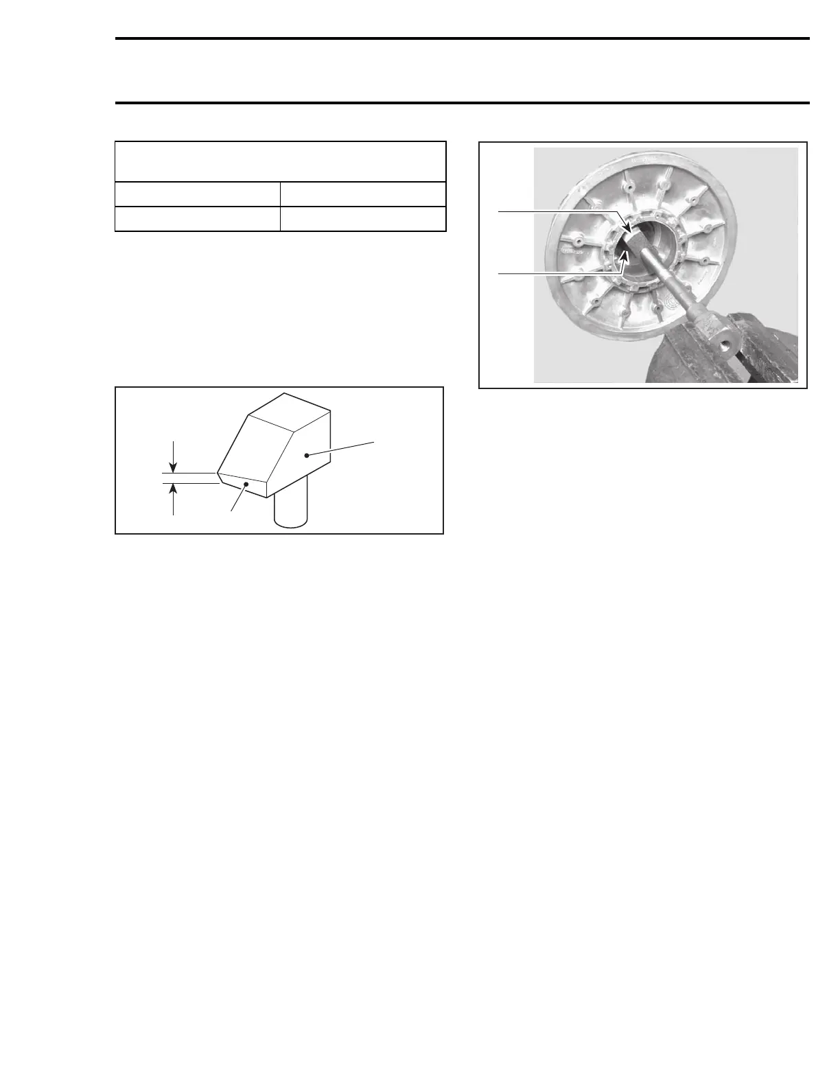
Mount screw head of new puller (P/N 529 035
524) in a vise.
Turn pulley half by hand to extract old bushing.
Before bushing installation, file sliding half bore to
remove burrs from crimping areas.
Coat bushing outside diameter with Loctite 609
(P/N 413 703 100). Place new bushing on sliding
half and slightly tap to engage squarely the bush-
ing in the sliding.
ASSEMBLY
Cam Slider Shoe
When replacing slider shoes no. 10 and no. 11,al-
ways install a new set (3 shoes) to maintain equal
pressure on the cam.
Install slider shoes as per following photo. Red
slider shoes are being used for reverse and black
ones for forward.
mmr2004-Rev 229

 Loading...
