Section 06 TRANSMISSION
Subsection 04 (PULLEY DISTANCE AND ALIGNMENT)
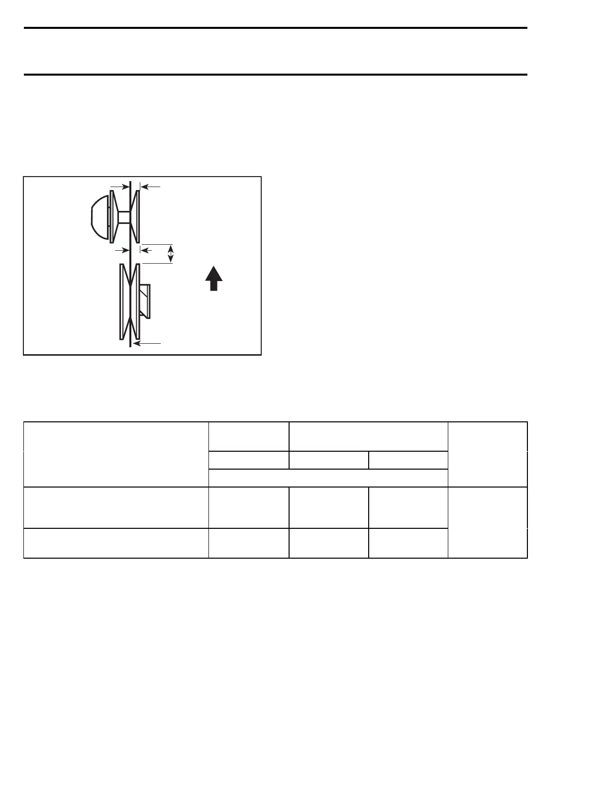
Measuring Procedure
Using Straight Bar
Always measure distances X and Y from the far-
ther straight bar side (including its thickness to the
fixed half edge).
A00D0WA
1
2
Z
X
Y
TYPICAL
1. Straight bar
2. Front of vehicle
The distance Y
must
exceed distance X to com-
pensate for the twist due to the engine torque.
Drive Belt Deflection
NOTE: When pulley distance and alignment are
adjusted to specifications, refer to DRIVE BELT to
adjust drive belt deflection.
CAUTION: This section deals mainly with ad-
justment procedures. For complete assembly
requirements, refer to the proper ENGINE or
TRANSMISSION installation section.
PULLEY ALIGNMENT AND DISTANCE SPECIFICATIONS CHART
PULLEY
DISTANCE
OFFSET
Z X Y-X
MODEL
± 0.50 mm (.020 in)
ALIGNMENT
BAR
P/N
ALL REV SERIES MODELS WITH
FORMULA VSA OR FORMULA VSA
RER
19.0 (0.748) 37.0 (1.456) 1.5 (0.060)
ALL REV SERIES MODELS WITH HPV
VSA
20.0 (0.787) 37.0 (1.456) 1.5 (0.060)
529 035 831
236 mmr2004-Rev

 Loading...
