Section 07 ELECTRICAL SYSTEM
Subsection 04 (ELECTRIC STARTER)
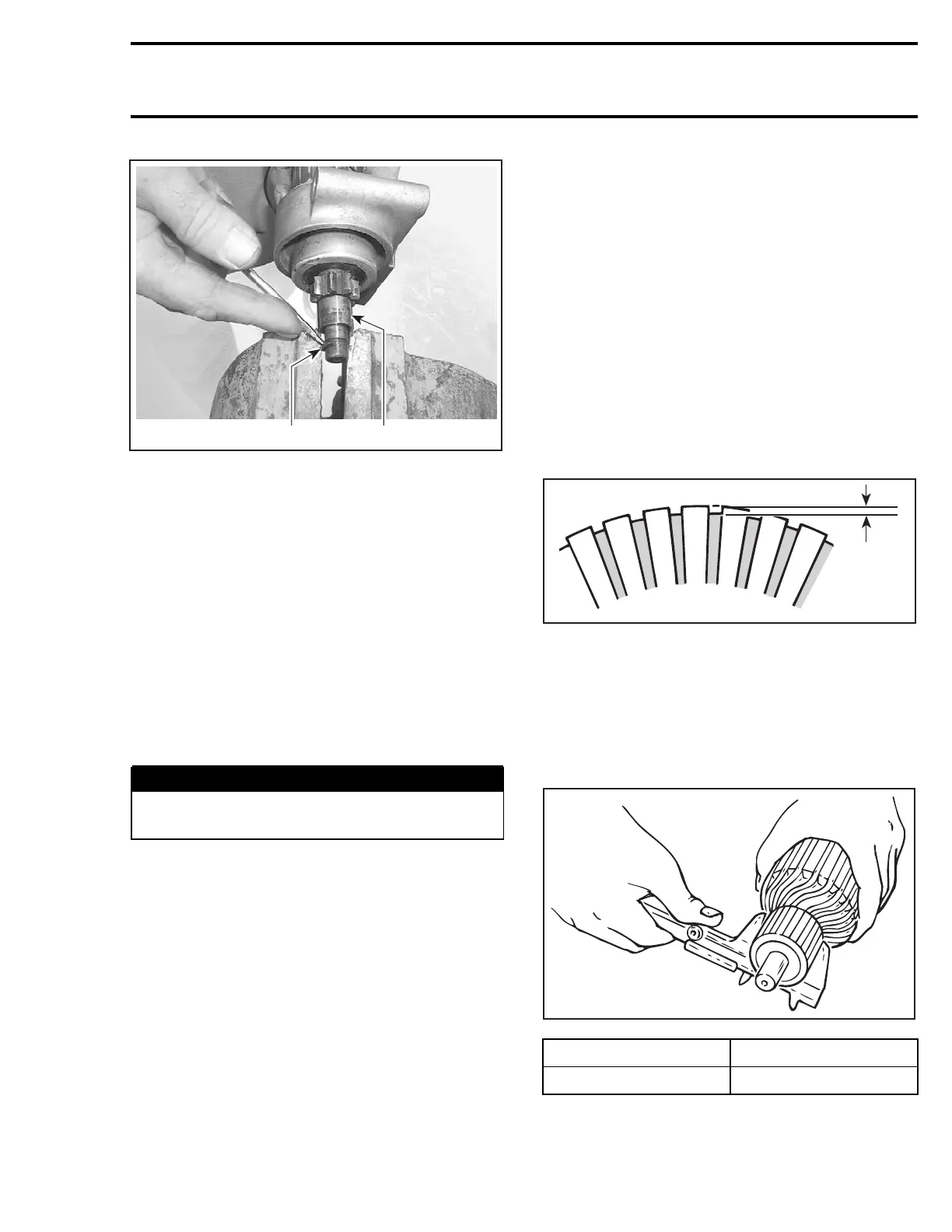
A32E20A
2
1
1. Collar
2. Snap ring
Turn starter clutch no. 6 clockwise to remove it
from armature assembly no. 11.
Pull housing from armature.
CLEANING
CAUTION: Yoke assembly and drive unit as-
sembly must not be immersed in cleaning sol-
vent.
Clean brushes and holders with a clean cloth
soaked in solvent. Brushes must be dried thor-
oughly with a clean cloth.
Blow brush holders clean using compressed air.
WARNING
Always wear safety glasses when using com-
pressed air.
Remove dirt, oil or grease from commutator using
a clean cloth soaked in suitable solvent. Dry well
using a clean and dry cloth.
Clean engine ring gear teeth and drive unit (clutch).
NOTE: Bushings or bearings must not be cleaned
with grease dissolving agents.
Immerse all metal components in cleaning solu-
tion. Dry using a clean and dry cloth.
INSPECTION
All Models except 4-Tec Engines
Armature
NOTE: An ohmmeter may be used for the follow-
ing testing procedures, except for the one con-
cerning the shorted windings in the armature.
Check the commutator for roughness, burnt or
scored surface. If necessary, turn the commuta-
tor on a lathe, enough to remove grime only.
Check the commutator for mica depth. If the
depth is less than 0.20 mm (.008 in), undercut
the mica. Be sure that no burrs are left and no
copper dust remains between the segments after
the undercutting operation is completed.
F01H0RA
1
1. Commutator undercut 0.20 mm (.008 in)
Check the commutator out-of-round condition
with V Blocks and an indicator. If the commutator
out-of-round is more than 0.40 mm (.016 in), the
commutator should be turned on a lathe.
Check commutator outer diameter. If less than
specified value, replace.
A03E06A
MODEL WEAR LIMIT
All models 27 mm (1.063 in)
mmr2004-Rev 265

 Loading...
