Section 07 ELECTRICAL SYSTEM
Subsection 01 (IGNITION TIMING)
IGNITION TIMING
593, 593 HO, 593 HO SDI and 793 HO Engines
Normally ignition timing adjustment should not be
required. It has been set at factory and it should
remain correctly adjusted since every part is fixed
and not adjustable. The only time the ignition tim-
ing might have to be changed would be when re-
moving and reinstalling the magneto housing, re-
placing the crankshaft, the magneto flywheel, the
trigger coil or the MPEM or ECM. If the ignition
timing is found incorrect, first check for proper
crankshaft alignment. This might be the indication
of a twisted crankshaft. Refer to LEAK TEST AND
ENGINE DIMENSION MEASUREMENT.
Theignitiontimingcanbecheckedwitheitherthe
engine hot or cold. Also, the ignition timing is to
be checked at 3500 RPM with a timing light.
Engine retard timing varies depending on engines/
models for their first hours of operation.
ENGINE/MODELS
ENGINE RETARD TIMING
(°)/DURATION (h)
593 -3°/1 h
593 HO, 593 HO SDI -2°/3 h
793 HO -2°/3 h
NOTE: Between 3000 and 4000 RPM, the spark
advance does not change. So when checking igni-
tion timing at 3500 RPM, a change in engine speed
within ± 500 RPM will not affect the timing mark
when checked with the timing light.
SCRIBING A TIMING MARK
• Clean the area around the MAG spark plug, and
remove it.
• Install the TDC gauge in the spark plug hole,
(magneto side) and adjust as follows:
– Position the MAG piston at approximately
TDC.
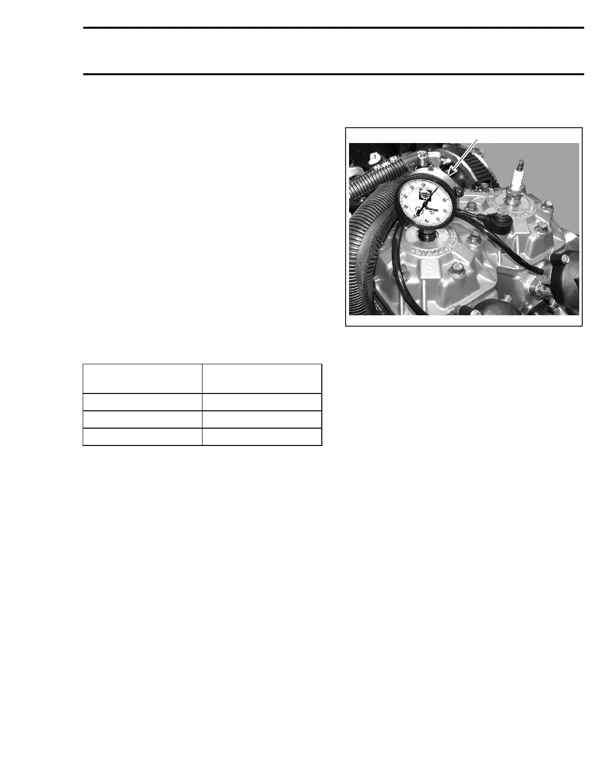
1
A32C9GA
TYPICAL
1. TDC gauge on MAG side
– Assemble the gauge to the adaptor and
tighten the roller lock nut. Do not tighten
the adaptor lock nut.
– Screw the adaptor into the spark plug hole
and tighten to prevent movement in the plug
hole.
– Position the dial face toward the PTO. Move
the gauge down until the needle just begins
to move, then move down a further 5 or 6
mm (approximately 1/4 in). Tighten adaptor
lock nut by hand.
• Locate the piston TDC position as follows:
– Slowly rotate the drive pulley back and forth
across TDC while observing the needle.
Note that the needle stops moving only as
the piston is changing direction.
– Rotate the dial face so that «0» is in line with
the needle when it stops moving.
– Again, slowly rotate the drive pulley back and
forth across TDC and adjust the dial face to
«0», until the needle always stops exactly at
«0» before changing direction.
–«0» now indicates exact TDC.
• Rotate the drive pulley clockwise, one-quarter
turn then carefully rotate it counterclockwise
until the needle indicates the specified mea-
surement, indicated in TECHNICAL DATA.
• Twist a wire as shown and use it as a pointer.
Install the wire on upper starter bolt.
mmr2004-Rev 251

 Loading...
