Section052–TEC ENGINE MANAGEMENT
Subsection 02 (COMPONENT INSPECTION AND ADJUSTMENT)
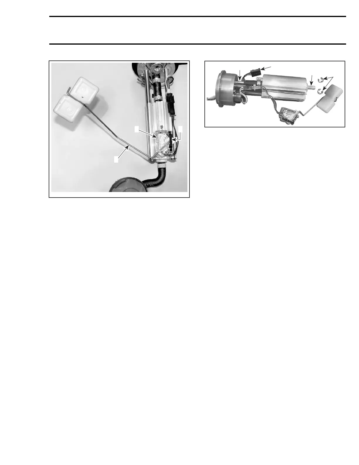
A33I0GA
1
2
3
1. Float
2. Retainer
3. Resistor card
Install a new gasket, then reinstall fuel pump mod-
ule as explained above.
Pump Ass’y Kit (P/N 861 302 600)
Remove fuel pump module as explained above.
Disconnect fuel pickup hose from pump inlet nip-
ple.
Unlock and remove lock plate of resistor card ass’y
if so equipped.
Disconnect pump electric connector.
Disconnect pump outlet hose from pump module
flange nipple.
Remove E-clips. Slide pump ass’y out of retaining
rods. Make sure that float and resistor card ass’y
slides along the aluminum extrusion.
1
A32I0YA
2
3
4
TYPICAL
1. Pump inlet nipple
2. Pump electric connector
3. Pump module flange nipple
4. E-clips
Reverse removal procedure for installation.
Install a new gasket, then reinstall fuel pump mod-
ule as explained above.
Regulator Kit (P/N 861 302 100)
Remove fuel pump module as explained above.
Remove 2 screws retaining regulator to pump
module flange.
Replace O-rings with new ones. Install them in
pump module flange bore.
CAUTION: Regulator O-rings must be installed
in pump module flange bore.
Reverse removal procedure for installation.
Install a new gasket, then reinstall fuel pump mod-
ule as explained above.
FUEL RAIL
Pressure at fuel rail is supplied and controlled by
thefuelpumpmodule. RefertoFUELPUMPfor
pressure test.
Fuel Rail Replacement
Removal
Release the fuel pressure in the system using
B.U.D.S. Look in the Activation tab.
Disconnect fuel hose at the connector.
Wrap a rag around the hose end to prevent rail
draining.
mmr2004-Rev 185

 Loading...
