Section 08 REAR SUSPENSION
Subsection 01 (SC-10 SUSPENSION)
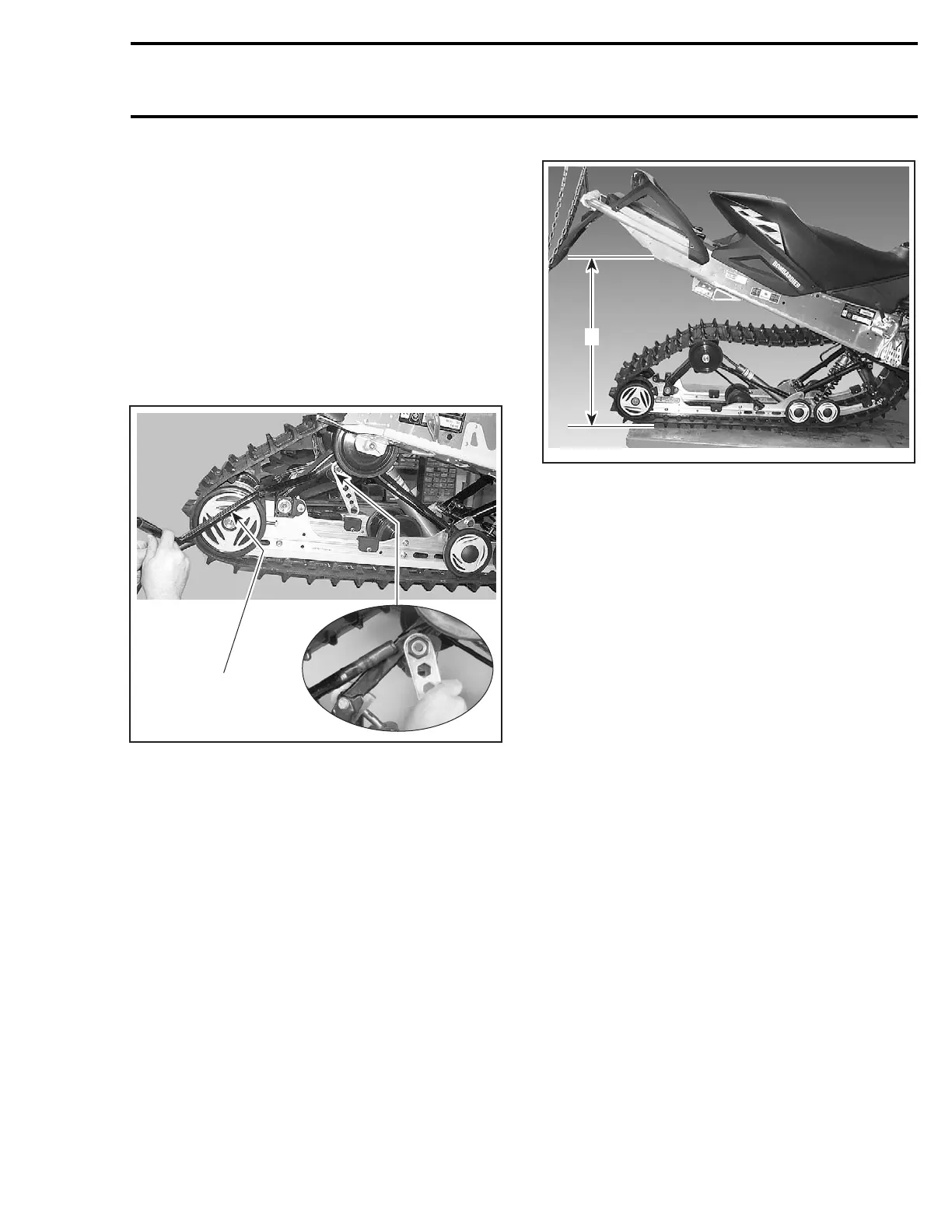
Remove the front idler wheels to gain access to
the axle retaining self-locking screws no. 6.Fol-
low the instructions provided in this section to un-
fasten these screws. Slide out the axle and re-
move the shock.
Rear Spring
Decrease spring preload by turning cams accord-
ingly.
Slightly turn adjusting cam to expose spring end.
Using spring installer (P/N 529 005 000), remove
both springs from adjusting cams.
529 005 000
A33F43A
Remove spring no. 2 ends from adjusting cams.
Unbolt rear arm top axle from chassis.
SUSPENSION ASSEMBLY
REMOVAL
Decrease spring preload by turning cams no. 19
accordingly.
Lift rear of vehicle and support it off the ground.
Loosen track tension.
Remove rear arm top axle screws no. 7 from chas-
sis.
Lift rear of vehicle at least 1 m (3 ft).
A33F46A
A
TYPICAL
A. At least 1 m (3 ft)
Remove screws no. 6 retaining front arm to tun-
nel.
Remove suspension.
Self-Locking Screws
CAUTION: These self-locking screws must al-
ways be replaced by new ones every time they
are removed.
NOTE: To prevent axle from turning when un-
screwing self-locking screws no. 6 and no. 7,
proceed as follows:
– Remove one self-locking screw then install a
10 mm shorter non-self-locking one in place.
Torque as specified in exploded view.
– Remove the opposite self-locking screw.
– Remove the temporary installed non-self-lock-
ing screw.
– If it doesn’t work, heat screw head to melt
threadlocker.
DISASSEMBLY AND ASSEMBLY
Inspect track thoroughly before reinstalling sus-
pension. Refer to TRACK.
Rear Arm
At installation, rear arm no. 1 stroke limiter must
be on rear side.
mmr2004-Rev 289

 Loading...
