Home
Ski-Doo
Snowmobiles
REV Series
Ski-Doo REV Series Shop Manual
5
of 1
of 1 rating
436 pages
Give review
Manual
Specs
To Next Page
To Next Page
To Previous Page
To Previous Page
Loading...
Section
12
WIRING
DIAGRA
M
Subsec
tion
0
1
(
WIRIN
G
DIA
GRA
M
S)
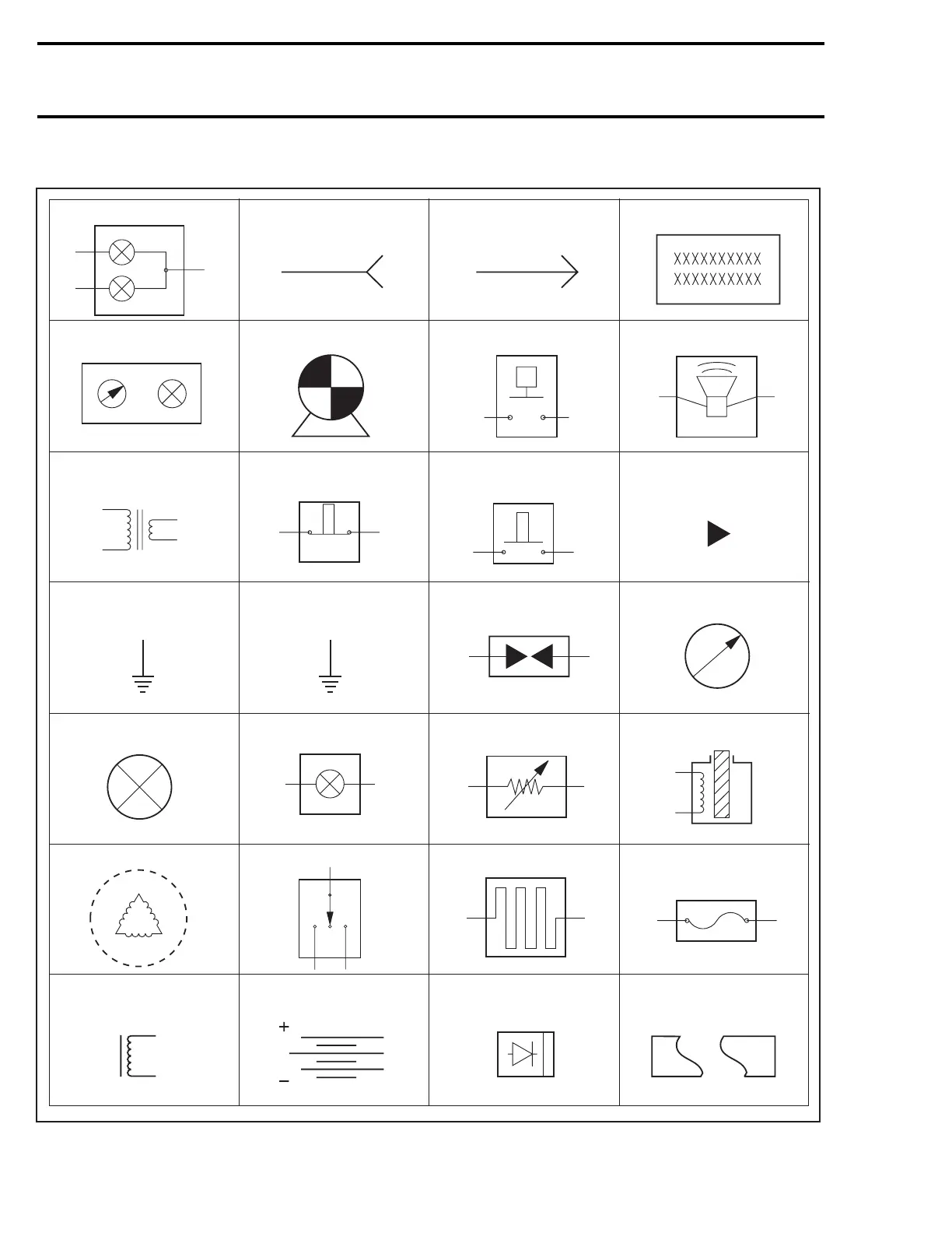
SYMBOL
S
DES
CRIP
TIO
N
Beam and tail light
Female terminal
Male terminal
Electronic module
Meter
Electric motor
Low level sensor
Buzzer
Ignition coil
Normally close
switch
Male terminal
on instrument
Engine
ground
Spark plug
Meter movement
Bulb
Pilot
Analog
sensor
Solenoid
valve
Magneto (Delta)
3 position switch
Heating element
Fuse
Normally open
switch
Frame
ground
Frame
T
rigger coil
Battery
Diode
Par
t
ially illustrated
component
A00E9PS
412
mmr2004-Rev
422
424
Table of Contents
Default Chapter
4
Table of Contents
4
Safety Notice
12
Introduction
13
Vehicle Identification Number
18
Engine Serial Number
18
List of Abbreviations Used in this Manual
18
Arrangement of this Manual
20
Threadlocker
23
Stripped Thread Repair
24
Gasket Compound
25
Mounting on Shaft
25
Case-In Components
26
Tightening Torques
26
Tools and Service Products
30
Service Tools
30
Engine - Mandatory Tools
31
Engine - Recommended Tools
33
Transmission - Mandatory Tools
39
Transmission - Recommended Tools
40
Suspension - Mandatory Tools
44
Suspension - Recommended Tools
45
Vehicle - Recommended Tools
48
Service Products
50
Maintenance
58
Maintenance Chart
58
Storage
61
General
61
Fuel Stabilizer
61
Engine Lubrication
61
Engine Compartment
62
Pulley Protection
62
Countershaft Lubrication
62
Battery
62
Vehicle Cleaning
62
Rags in Air Intake and Exhaust System
62
Vehicle Protection
62
Preseason Preparation
63
Fuel Filter Replacement
63
Throttle Body Cleaning(on so Equipped Models)
64
Carburetor Cleaning(on so Equipped Models)
64
Air Filter Cleaning
64
Rags in Air Intake and Exhaust System
64
Cleaning of Drive and Driven Pulleys
64
Cleaning of Brake Disk
64
Drive Belt Condition
64
Spark Plugs
64
Troubleshooting
65
Engine
65
Engine Leak Verification Flow Chart
76
Fuel and Oil Systems
77
Transmission and Brake System
80
Transmission
80
Brake System
87
Hydraulic Brake
87
Electrical System
88
Suspension and Track
100
Engine
104
Ho, 593 Ho Sdi and 793 Ho Engine Types
104
Exhaust System
104
Tuned Pipe
105
Manifold
105
Muffler
105
Engine System
107
Removal from Vehicle
108
Inspection
111
Installation
111
Top End
112
Troubleshooting
116
Component Removal with the Engine Installed
116
Cleaning
116
Rave Valve Basic Operation
116
Disassembly
117
Inspection
121
Assembly
122
Bottom End
127
Cleaning
130
Disassembly
130
Inspection
131
Assembly
131
Break-In
136
Engine Leak Test and Dimension Measurement
137
Leak Test
137
Preparation
137
Procedure
137
Finalizing Reassembly
139
Engine Leak Verification Flow Chart
140
Engine Dimension Measurement
141
Cylinder Head Warpage
141
Cylinder Taper
141
Cylinder out of Round
141
Combustion Chamber Volume Measurement
141
Used Piston Measurement
143
Cylinder/Piston Clearance
143
Ring/Piston Groove Clearance
145
Ring End Gap
145
Crankshaft Deflection
145
Connecting Rod Big End Axial Play
146
Crankshaft End-Play
146
Checking Crankshaft Alignment
146
Magneto System
147
General
149
Cleaning
149
Disassembly
149
Assembly
150
Oil Injection System
152
General
153
Oil Type
153
Oil System Leak Test
153
Oil Pump Identification
154
Cleaning
154
Disassembly
154
Assembly
155
Adjustment
156
Checking Operation
157
Liquid Cooling System
158
Cooling System Leak Test
160
Inspection
160
Draining the System
160
Disassembly and Assembly
160
Cooling System Refilling Procedure
162
Rewind Starter
163
Inspection
164
Removal
164
Rope Replacement
164
Disassembly
164
Assembly
165
Installation
167
Carburetor and Throttle Cable
168
Carburetor Tm Type
168
Identification
169
Removal
169
Cleaning and Inspection
170
Disassembly and Assembly
171
Carburetor Adjustments
172
Installation
174
Dpm
175
Testing
175
Parts Removal and Installation
175
Dpm Manifold Testing
176
Throttle Cable
178
Throttle/Oil Pump Cable Removal
178
Throttle/Oil Pump Cable Installation
178
Throttle Cable Adjustment
178
Fuel Tank and Fuel Pump
180
Fuel Filter
182
Fuel Tank
182
Impulse/Fuel Lines Spring Clips (All Models)
183
Float-Type Fuel Level Gauge
184
Electric Fuel Level Sensor
184
Fuel Level Sensor Screws
184
Fuel System Pressurization
184
Fuel Pump
185
Removal
186
Pump Verification
186
Cleaning and Inspection
186
Installation
186
05 2-Tec Engine Management
187
Overview
187
Operating Principle
188
Air Induction
188
Fuel Delivery System
188
General
188
Component Description
188
Engine Management System (Ems)
189
Ems - General Functions
190
Ecu - Engine Management Functions
191
Electronic Fuel Injection
192
Ignition Timing
192
Electronically Controlled Rave
192
Knock Sensor
192
Engine Modes of Operation
192
Flooded Engine (Drowned Mode)
192
Monitoring System
192
Limp Home Modes
193
Diagnostic Mode
193
Charging System
193
Magneto System
193
Double Ignition Coil
193
Trigger Coil
194
Component Inspection and Adjustment
195
General
195
Fuel System
195
Electrical System
196
Resistance Measurement
197
Engine Connector Pin-Outs
198
Air Induction System
199
Throttle Body
199
Fuel Delivery
202
Fuel Pump
203
Fuel Rail
207
Fuel Injectors
208
Electronic Management
210
Ecm Replacement
210
Engine Wiring Harness
211
Throttle Position Sensor (Tps)
211
Crankshaft Position Sensor (Cps)
214
Air Temperature Sensor (Ats)
215
Coolant Temperature Sensor (Cts)
215
Air Pressure Sensor (Aps)
216
Exhaust Gas Temperature Sensor (Egts)
217
Knock Sensor (Ks)
218
E-Rave Solenoid
219
Double Ignition Coil
219
Tdc Setting (Top Dead Center)
221
Capacitor
221
Engine Start/Rer Button Verification
222
Dess Switch Verification
222
Spark Plugs
222
Cranking System
223
Diagnostic Procedures
224
General
224
Troubleshooting
224
2-Tec System Fault Codes
228
Transmission
230
Drive Belt
230
Application Chart
230
Inspection
230
Checking Neutral Function
230
Rotation Direction
230
Drive Belt Height Measurement and Adjustment
231
Drive Belt Deflection Measurement (Reference Only)
233
Drive Pulley
235
General
236
Removal
236
Disassembly
236
Cleaning
238
Inspection
238
Assembly
240
Installation
243
Drive Pulley Adjustment
244
Driven Pulley
246
Formula Rer
246
Removal
247
Disassembly
247
Cleaning
247
Inspection
247
Bushing Replacement
248
Assembly
248
Installation
249
Adjustment
250
Hpv Vsa
251
Removal
252
Disassembly
252
Cleaning
252
Inspection
252
Assembly
252
Installation
253
Adjustment
253
Pulley Distance and Alignment
254
General
254
General Procedure
254
Pulley Alignment and Distance Specifications Chart
255
Brake
257
Hydraulic Brake
257
Brake Fluid
258
Master Cylinder
258
Caliper
258
Brake Pads
259
Brake Disc
260
Countershaft Bearing
260
Countershaft
261
Brake Light Switch
261
Bleeding
262
Chaincase
263
Removal and Disassembly
264
Inspection
264
Gear Ratio Modification
264
Installation and Assembly
265
Drive Chain Adjustment
265
Adjustment
266
Drive Chain
267
Silent Chain
267
Electrical System
268
Ignition Timing
268
Scribing a Timing Mark
268
Checking Ignition Timing
269
Changing Timing
270
Spark Plugs
274
Disassembly
274
Spark Plug Installation
274
Spark Plug Tightening Torque
274
Battery
275
General
275
Removal
275
Cleaning
275
Inspection
275
Battery Charge Testing
276
Battery Storage
276
Activation of New Battery
276
Battery Charging
276
Installation of Battery
276
Cable Terminal Installation
277
Electric Starter
279
Removal
280
Disassembly
280
Cleaning
281
Inspection
281
Assembly
283
Installation
284
Testing Procedure
285
General
285
Checking Calibration Program
288
Changing Mpem Calibration Program
291
System Testing
292
Inspection of Heating Elements
299
Headlight and Accessories System Testing
300
Rear Suspension
301
1 Sc-10Suspension
304
Component Removal and Installation
304
Suspension Assembly Removal
305
Disassembly and Assembly
305
Shock Absorber Inspection
307
Installation
308
Ride Adjustment
308
Lubrication
308
2 Sc-10Iiisuspension
312
Component Removal and Installation
312
Suspension Assembly Removal
313
Disassembly and Assembly
314
Shock Absorber Inspection
316
Hpg T/A Shock Servicing
317
Installation
325
Ride Adjustment
325
Lubrication
325
Drive Axle
326
Removal
327
Assembly
328
Lubrication
329
Adjustment
330
Track
331
Track Type Application
331
General
331
Inspection
331
Removal
331
Installation
331
Adjustment
331
Steering/Front Suspension
334
Steering System
334
Disassembly and Assembly
336
Inspection
339
Adjustment
339
Steering Adjustment (Skis)
343
Lubrication
345
Front Suspension
346
General Inspection
347
Disassembly
347
Inspection
351
Installation
351
Body/Frame
356
Body
356
Installation and Adjustment
356
Headlamp Beam Aiming
356
Bulb Replacement
356
Decal
357
Windshield
357
Guard
358
Wiring Harness
358
Cables
358
Tubing
358
Plastic Maintenance and Repair
358
Maintenance
358
Repair
359
Frame
360
Frame Cleaning
360
Frame Welding
360
Frame Component Replacement
360
Technical Data
361
Si* Metric Information Guide
361
Engines
362
Vehicles
390
Technical Data Legends
418
Engine Legend
418
Vehicle Legend
419
Wiring Diagram
420
Wiring Diagrams
420
Wiring Diagram Legend
420
Wire Colors
420
Connector Housing Area
420
Housing Reference Per Area
420
Wire Location in Connector Housing
421
Symbols Description
423
Unpluging Connectors
424
Tab and Receptacle Connectors Removal
424
Tab and Receptacle Connectors Installation
430
Other manuals for Ski-Doo REV Series
Operator's Guide
227 pages
5
Based on 1 rating
Ask a question
Give review
Questions and Answers:
Need help?
Do you have a question about the Ski-Doo REV Series and is the answer not in the manual?
Ask a question
Ski-Doo REV Series Specifications
General
Chassis
REV
Track Width
15 in
Fuel Capacity
10.6 gal
Seating Capacity
1
Reverse
Available on most models
Electric Start
Available on most models
Related product manuals
Ski-Doo REV series 2007
255 pages
REV G4 Trail/Crossover E-TEC Series
291 pages
Ski-Doo Mach Z
356 pages
Ski-Doo MACH 1 1997
219 pages
Ski-Doo MACH Z 1997
219 pages
Ski-Doo MX Z 670 1998
398 pages
Ski-Doo Summit 670 1998
398 pages
Ski-Doo SKANDIC 380 1997
926 pages
Ski-Doo Tundra II LT 1997
926 pages
Ski-Doo Formula 583 DL 1998
398 pages
Ski-Doo Grand Touring 700/SE
304 pages
Ski-Doo Grand Touring 500 1998
398 pages

 Loading...
