Section 07 ELECTRICAL SYSTEM
Subsection 04 (ELECTRIC STARTER)
1
2
A32E22A
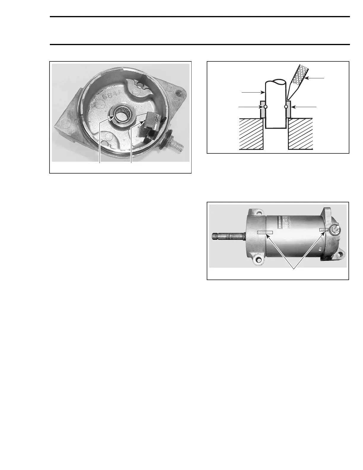
1. Roller bearing
2. Positive brush
Overrunning Clutch
The pinion of the overrunning clutch should turn
smoothly in a clockwise direction, and should not
slip in a counterclockwise direction. If defective,
replace.
Check the pinion teeth for wear and damage. If
defective, replace.
Relay
Inspect connections and clean as necessary. Re-
lay condition can be checked with an ohmmeter.
Install test probes on large connectors of relay
when it is activated (+ on RED/GREEN wire and
- on relay body for the fan cooled models and - on
the BLACK wire for liquid cooled models).
IMPORTANT: Nocurrentmustbepresentonlarge
cables when using ohmmeter, otherwise meter
could be damaged.
ASSEMBLY
Reverse the order of disassembly to reassemble
starter. However, attention should be paid to the
following operations.
Prior to assembling, coat sliding surfaces on arma-
ture shaft splines, overrunning clutch and bushing
with synthetic grease (P/N 413 711 500).
After placing collar no. 3 on armature shaft no. 11,
fit new snap ring no. 2 on armature shaft, then
make sure that it is properly secured.
Slide collar no. 3 over snap ring no. 2 and secure
in place by punching it at two or three places.
A03E0EA
1
2
4
3
1. Armature shaft
2. Snap ring
3. Collar
4. Punch
Starter Housing Assembly and Starter Housing
Align previously traced indexing marks.
1
A32E21A
TYPICAL
1. Aligned indexing marks
Open brushes and slide over commutator.
Align end frame locating notch with yoke locating
protrusion and properly sit brush holder no. 13 into
housing no. 14.
mmr2004-Rev 267

 Loading...
