Section 09 STEERING/FRONT SUSPENSION
Subsection 01 (STEERING SYSTEM)
A02G0IA
1
2
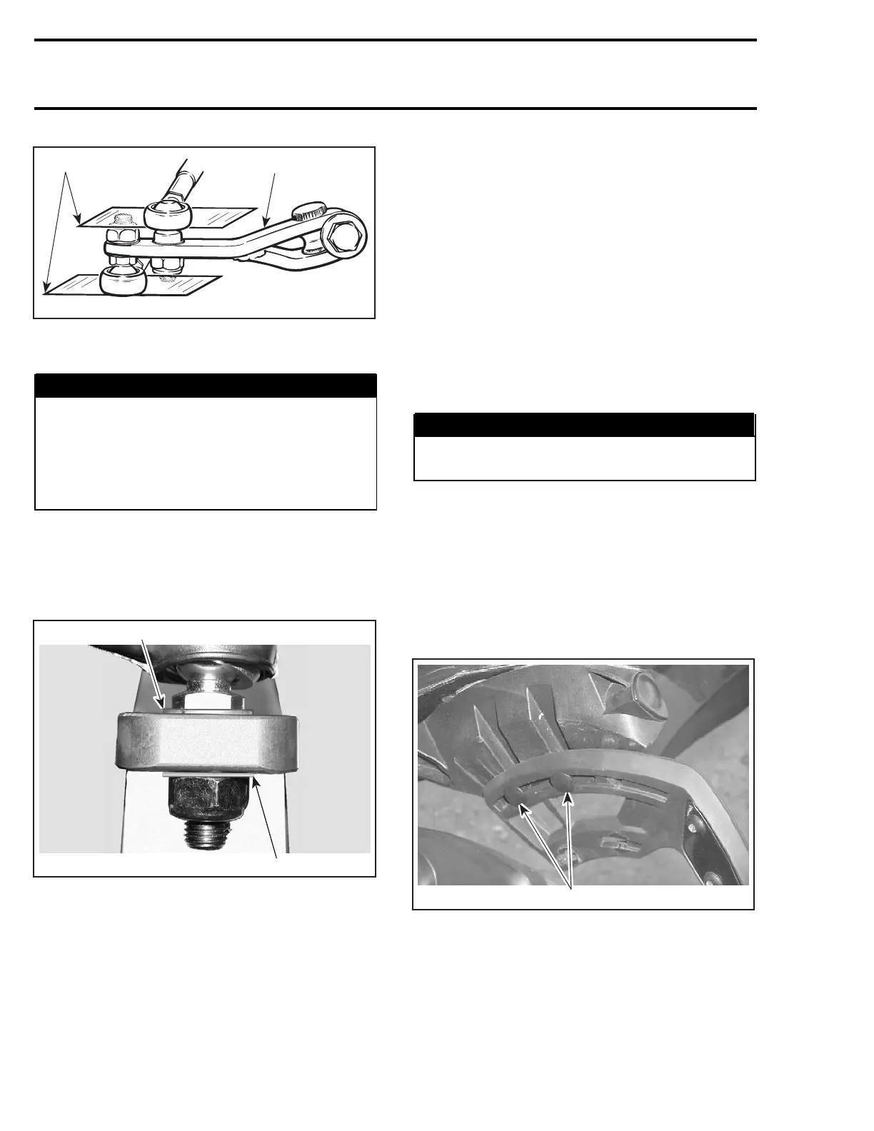
TYPICAL
1. Parallel with steering arm
2. Steering arm
WARNING
The cut off section of the ball joint must run
parallel with the swivel bar no. 9. When tight-
ening lock nuts, restrain ball joint with appro-
priate size wrench. The maximum external
threaded length not engaged in the tie rod
must not exceed 20 mm (25/32 in).
Hardened Washer
Install a hardened washer no. 7 on each side of
the ski leg and each side of the steering column
lever.
1
1
A33G0EA
TYPICAL
1. Hardened washers
INSPECTION
Check skis and runners for wear. Replace as nec-
essary. Refer to FRONT SUSPENSION.
Check the general condition of the steering sys-
tem components for wear. Replace if necessary.
Heating Grip Element
Refer to TESTING PROCEDURE for checking
heating element no. 13 of grip.
Ball Joint (left hand and right
hand threads)
Inspect ball joint ends no. 17 and no. 18 and small
tie rod ends for wear or looseness, if excessive,
replace them.
ADJUSTMENT
Steering Column Position Adjustment
Some Models
WARNING
Do not drill additional holes to customize
steering column position.
Steering column position is adjustable. Proceed
as follows.
There are 2 positions.
NOTE: Following procedure describes how to
change steering column position from rearward
to forward position.
Unscrew 4 bolts retaining windshield assembly to
handlebar. Remove windshield assembly.
A33H12A
1
ONE SIDE SHOWN — REARWARD POSITION
1. Bolts retaining windshield assembly
Remove cap no. 3 or steering padding no. 23 ac-
cording to model and remove console cap.
326 mmr2004-Rev

 Loading...
