Section04ENGINE
Subsection 03 (MAGNETO SYSTEM)
A03C1JB
420 876 080
1
TYPICAL
1. 30 mm socket
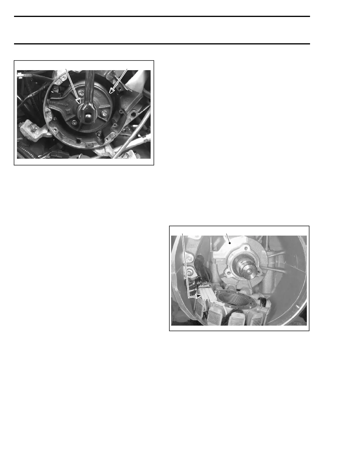
To remove magneto flywheel, install crankshaft
protector (P/N 420 876 557) on crankshaft end.
Screw puller (P/N 529 035 547 ) into puller ring.
– Tighten puller bolt and at the same time, tap on
bolt head using a hammer to release magneto
flywheel from its taper.
Stator
NOTE: Always check stator no. 6 before changing
it, refer to TESTING PROCEDURE.
Remove:
– magneto flywheel no. 3
– all Allen socket screws retaining stator to mag-
neto housing
– grommet from crankcase where trigger coil and
stator wires exit magneto housing.
Unplug the trigger coil connectors and pull the
wires through the grommet location.
NOTE: To pass the stator connector into the grom-
met location it is necessary to pass the trigger coil
connector first.
Unplug the stator connector and remove the sta-
tor.
Trigger Coil
NOTE: Always check trigger coils no. 5 before
changing them. Refer to OVERVIEW section.
To replace the trigger coil(s), remove the following:
– magneto flywheel no. 3
– Air intake silencer to allow an access to the trig-
ger coil connectors (if necessary).
– Disconnect trigger coil connector housing(s).
– grommet from crankcase where trigger coil
wire(s) exit(s) magneto housing.
– retaining screws no. 4.
– trigger coil(s) and carefully pull wires.
ASSEMBLY
Trigger Coil
For installation, reverse the removal procedure.
NOTE: It is important to remove the old silicon at
trigger coil location then apply new silicon. Screw
trigger coil then stick the trigger coil wires in the
silicon.
Stator
Insert the stator connector into crankcase grom-
met then the trigger coil connector(s).
Install the grommet on crankcase
Position stator no. 6 so that its wire protectors are
over crankcase recess.
1
A32E0KA
2
1. Crankcase recess
2. Wire protectors
NOTE: During installation, make sure the stator
harness is located on the left side.
Apply Loctite 243 on threads of stator screws then
torque them to 9 N•m(80lbf•in).
Reinstall all other removed parts.
124 mmr2004-Rev

 Loading...
