Section 05 2–TEC ENGINE MANAGEMENT
Subsection 02 (COMPONENT INSPECTION AND ADJUSTMENT)
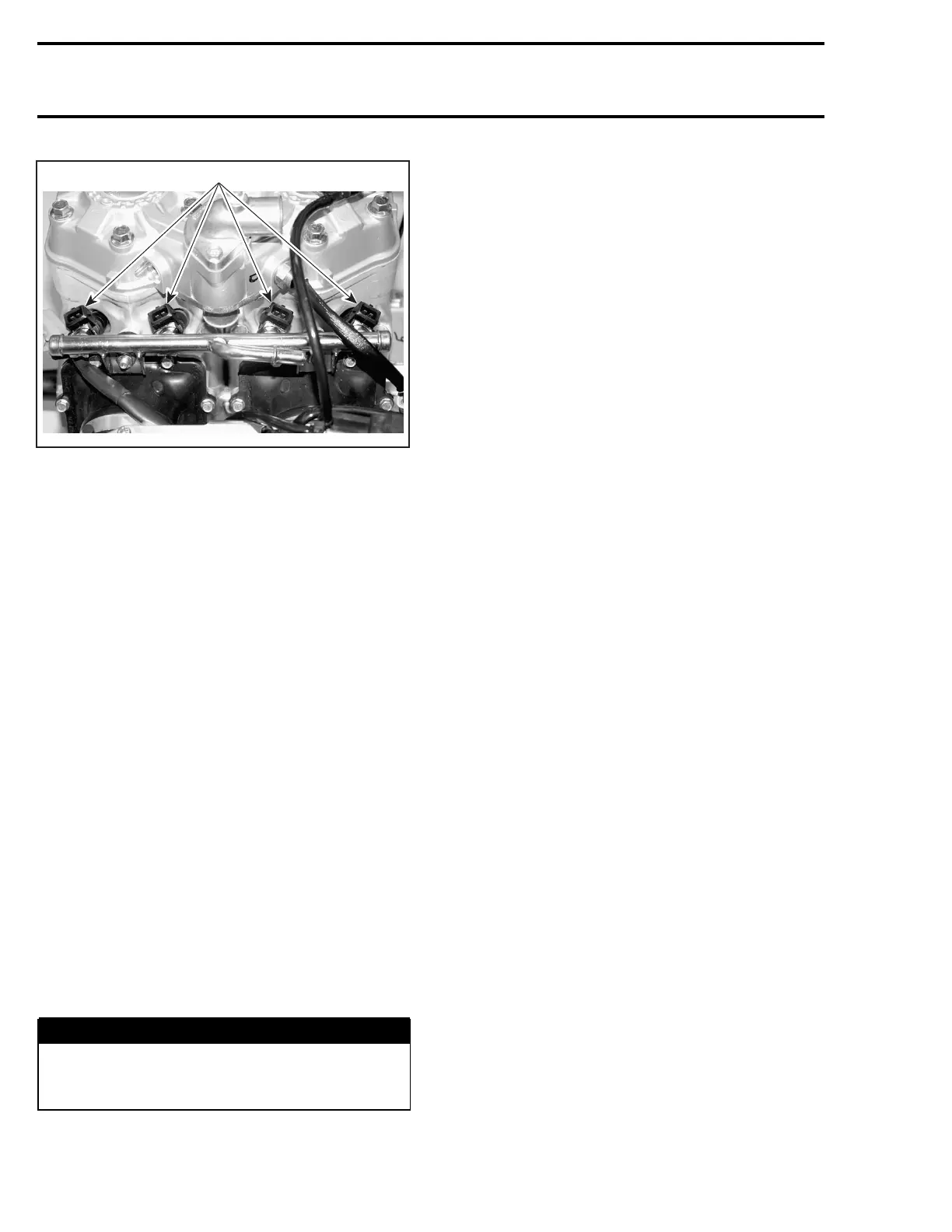
1
A32C9MA
1. Fuel injectors
Disconnect wiring harness from the four fuel in-
jectors.
Cut tie raps and remove the wiring harness from
the fuel rail.
Unscrew rail retaining nuts.
Gently pull rail up by hand, working each side
slightly at a time.
Pull rail out with fuel injectors.
If necessary remove fuel injectors as described
below.
Installation
For installation, reverse the removal process but
pay attention to the following.
Replace O-rings with new ones.
A thin film of injection oil should be applied to
O-rings of fuel injectors to ease installation in cylin-
der.
Torque rail retaining nuts to 10 N•m(89lbf•in).
Make sure that injector clips are well in place.
Adddielectricgrease(P/N293550004)toinjector
electrical connector.
When installing fuel line connector to the fuel rail,
put some oil on the O-ring to ease installation.
WARNING
Perform a fuel pressure test and ensure that
there is no leak. Refer to FUEL PUMP above.
Run engine and check for leaks.
FUEL INJECTORS
Leakage Test
To perform a leakage test, the injectors and fuel
rail have to be removed from the engine. Refer to
REMOVALinFUELRAILREPLACEMENTforthe
procedure.
NOTE: Do not detach injectors from the fuel rail.
Reconnect the fuel line and the wiring harness.
Place each injector in a clean bowl.
Install the tether cord cap on the DESS post and
press the engine START/RER button to activate
the fuel pump.
Check for fuel leakage from the injector nozzle.
There should be less than 1 drop per minute. Per-
form the test for 2 minutes.
If not within specification, replace the fuel injec-
tor(s).
The leakage test is validated when performing the
FUEL DELIVERY SYSTEM DIAGNOSTIC FLOW
CHART elsewhere in this section.
Electrical Test
Tether cord cap must be on DESS post.
Using the vehicle communication kit (VCK) with
the B.U.D.S. software, energize the fuel injector
from the Activation section.
If the injector does not work, disconnect the plug
connector from the injector.
Install a temporary connector to the injector with
wireslongenoughtomaketheconnectionoutside
the engine compartment and apply voltage (12 V)
to this test harness.
This will validate the injector mechanical and elec-
trical operation.
If it does not work, replace it.
Wake up ECM using START button and measure
voltage between pin 1 (of injector on harness side)
and battery ground.
If 12 V is read, disconnect connector A from the
ECM and check continuity of circuit as per follow-
ing table.
186 mmr2004-Rev

 Loading...
