Section 09 STEERING/FRONT SUSPENSION
Subsection 01 (STEERING SYSTEM)
DISASSEMBLY AND ASSEMBLY
Grip
NOTE: These models feature an integrated heat-
ing element in the plastic sleeve of the grip no. 13.
CAUTION: Removing grip from handlebar
might damage the heating element. Do not
remove needlessly.
NOTE: If heating grip does not work and needs to
be replaced, the grip can be cut with a knife for
removal.
Throttle Side:
Unfasten windshield.
NOTE: Throttle lever housing no. 21 must come
off handlebar along with grip.
Remove cap no. 3 or steering padding no. 23 ac-
cording to model. Unplug RH harness on top of
steering column. Cut locking ties retaining RH har-
ness to handlebar.
Remove throttle lever housing cover no. 19.
1
A33G09A
1. Throttle lever housing cover
Remove circlip no. 24 from throttle cable housing.
Unfasten throttle cable from throttle lever, then
pull out throttle cable housing from throttle lever
housing no. 21.
Unscrew screws no. 10 and remove J-hook no. 12
from end of grip on so equipped models.
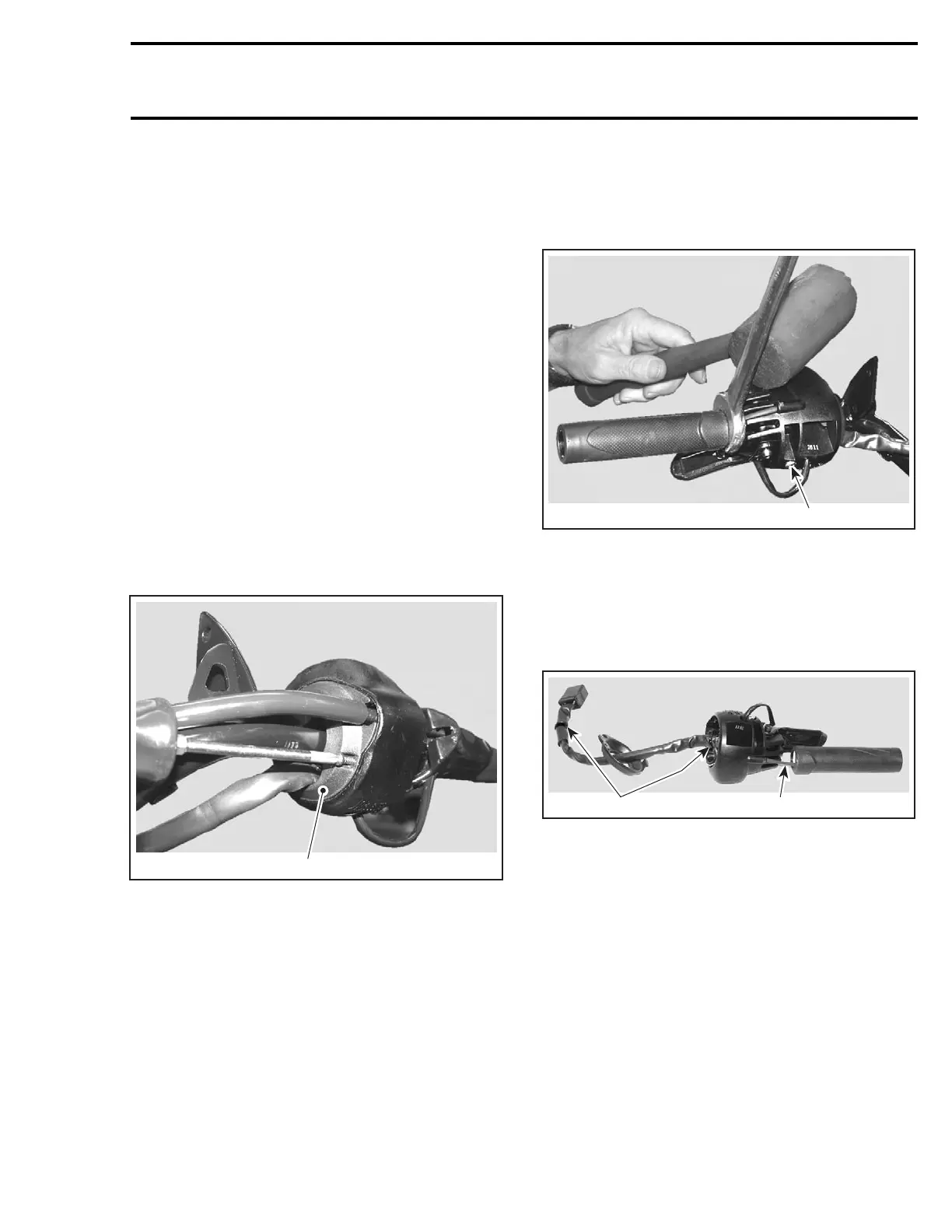
Loosen screw no. 20 retaining throttle lever hous-
ing to handlebar. See photo below.
Inserttheopensideofa23mm(7/8in)wrench
against the inner end of grip.
CAUTION: Pay attention not to damage wires
with the wrench.
Usingaplastichammer,taponthesideofthe
wrenchendtomakethegripslideout.
1
A33G0AA
1. Screw retaining throttle lever housing
Cut locking ties on harness. Using the mul-
tilock-terminal housing extraction tool AMP
(P/N 755430-2), push the 3 wires of the heat-
ing grip harness out of connector housing. Note
the position of the wires for reinstallation.
2
A33G0BA
1
1. Locking ties
2. Heatinggripharness
Pull heating grip harness out of throttle lever hous-
ing.
For installation refer to grip installation below.
Brake Side:
Unclip windshield.
Unplug connectors from brake light switch located
on master cylinder no. 22.
mmr2004-Rev 323

 Loading...
