Section 09 STEERING/FRONT SUSPENSION
Subsection 01 (STEERING SYSTEM)
1
A33G0FA
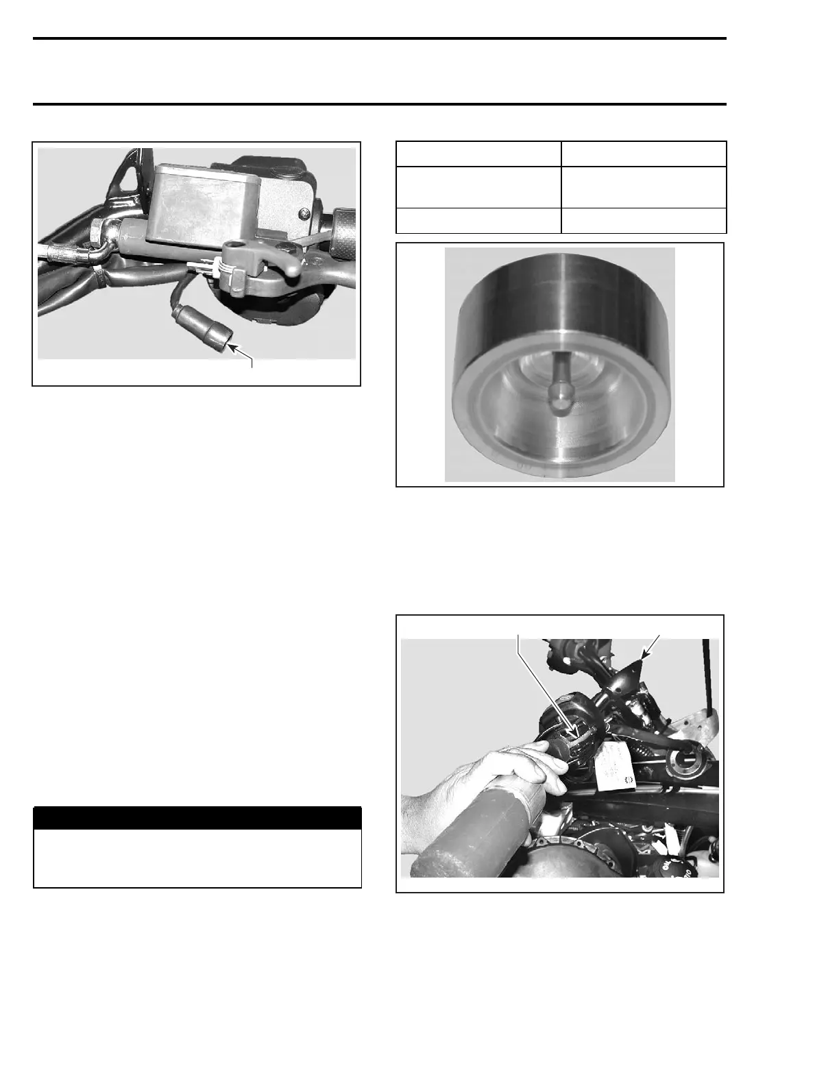
1. Connectors unplugged
Unplug LH harness on top of steering column.
Cut locking ties retaining brake light switch/heat-
inggripharnesstohandlebar.
Using the multilock-terminal housing extraction
tool AMP (P/N 755430-2), push the 3 wires of the
heating grip harness out of connector housing.
Note the position of the wires for reinstallation.
Pull heating grip wires out of brake light switch/
heating grip harness.
Inserttheopensideofa23mm(7/8in)wrench
against the inner end of grip.
CAUTION: Pay attention not to damage wires
with the wrench.
Using a plastic hammer, tap on the side of the
wrenchendtomakethegripslidingout.
Grip Installation:
Installation is the opposite procedure of the re-
moval but pay attention to the following.
Clean handlebar ends and inside of heating grip
with isopropyl alcohol. Let dry before installation.
WARNING
Handlebar end and inside of heating grip
must be clean and dry before installing heat-
ing grip to ensure proper adhesion.
Position grip on handlebar with its harness aligned
with windshield bracket. See next photo.
Use the appropriate insertion tool to properly in-
stall grip.
MODEL TOOL PART NUMBER
Models with straight
grips
529 035 897
Models with J-hooks 529 035 936
A32G2BA
CAUTION: Installing grip without the insertion
tool is likely to damage its heating element.
Position the insertion tool at the outside end of
grip.
Using a plastic hammer, tap on tool to push grip
on. Continue to tap until grip bottoms.
1
A33G0CA
2
1. Harness
2. Windshield bracket
Properly route harness then reinstall removed
parts.
324 mmr2004-Rev

 Loading...
