Section04ENGINE
Subsection 02 (ENGINE LEAK TEST AND DIMENSION MEASUREMENT)
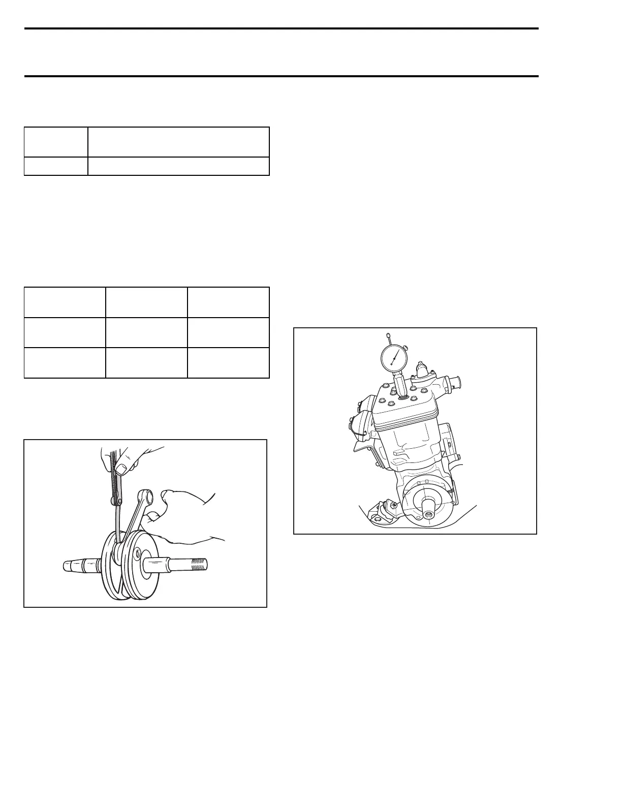
Crankshaft Deflection in Center of Crankshaft
ENGINE
TYPE
MAXIMUM IN CENTER OF
CRANKSHAFT mm (in)
All 0.08 (.0031)
NOTE: Crankshaft deflection cannot be correctly
measured between centers of a lathe.
If the deflection exceeds the specified tolerance,
crankshaft should be repaired or replaced.
CONNECTING ROD BIG END
AXIAL PLAY
ENGINE
TYPE
NEW PARTS
MIN. — MAX.
WEAR
LIMIT
593
0.39 - 0.74 mm
(.015 - .029 in)
1.20 mm
(.047 in)
593 HO/SDI,
693, 793 HO
0.31 - 0.67 mm
(.012 - .026 in)
1.20 mm
(.047 in)
Using a feeler gauge, measure distance between
thrust washer and crankshaft counterweight. If
the distance exceeds specified tolerance, repair or
replace the crankshaft.
A01C0SA
TYPICAL
CRANKSHAFT END-PLAY
End-play is not adjustable but it should be be-
tween 0.10 - 0.30 mm (.004 - .012 in).
CHECKING CRANKSHAFT
ALIGNMENT
Install a degree wheel (P/N 529 035 607) on crank-
shaft end.
Remove both spark plugs.
Install a TDC gauge (P/N 414 104 700) in spark plug
hole on MAG side.
BringMAGpistonattopdeadcenter.
Rotate degree wheel (not crankshaft) so that 360°
mark aligns with center of crankcase. Scribe a
mark on crankcase.
Remove TDC gauge and install it on center cylin-
der.
Bring PTO piston to top dead center. Degree
wheel must rotate with crankshaft.
0
90
80
70
60
50
40
30
20
10
1
8
0
0
A06C1TA
TYPICAL
Interval between cylinders must be 180° ±0.5.
Any other reading indicates a misaligned (twisted)
crankshaft.
120 mmr2004-Rev

 Loading...
