Section 06 TRANSMISSION
Subsection 05 (BRAKE)
529 035 699
A33D0WB
1
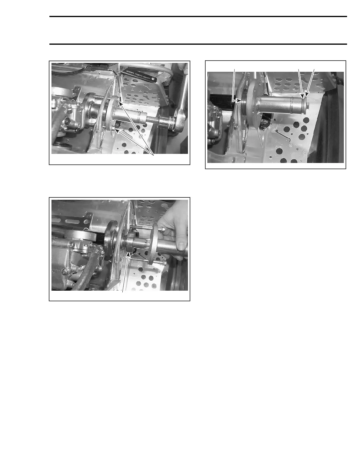
1. Screws
Install remover (P/N 529 035 699) on countershaft
for complete bearing no. 17 removal.
1
A33D0XA
TYPICAL
1. Bearing
Installation
Insert countershaft (with brake disc) from chain-
case side through countershaft support (driven
pulley side), then insert into chaincase.
Install countershaft bearing no. 17 using proper
tool.
To install bearing on countershaft, use remover
(P/N 529 030 100) and some flat washers of 3 mm
(1/8 in) total thickness. Using original retaining
screw and shouldered washer tighten until bear-
ing rests against circlip.
A33D0YA
213
1. Washers use as a 3 mm (1/8 in) spacer
2. Original retaining screw and shouldered washer
3. Bearing against circlip
Ensure that countershaft is properly aligned, then
tighten 3 retaining screws.
NOTE: A misaligned countershaft will result in dif-
ficulty to center the bearing in its support.
Torque castellated nut of upper sprocket to 45 to
75 N•m(33to55lbf•ft).
Close chaincase referring to CHAINCASE.
COUNTERSHAFT
REMOVAL
Proceed the same as for countershaft bearing re-
moval and then remove the countershaft no. 16.
Inspection
Check countershaft for bending, rust or other
damages. Replace if necessary.
Installation
The installation is the reverse of removal proce-
dure.
BRAKE LIGHT SWITCH
Removal
The brake light switch no. 18 is located near the
brake lever. To remove the switch, use the follow-
ing.
mmr2004-Rev 243

 Loading...
