Section04ENGINE
Subsection 02 (ENGINE LEAK TEST AND DIMENSION MEASUREMENT)
RING/PISTON GROOVE
CLEARANCE
Using a feeler gauge check clearance between
rectangular ring and groove. Replace piston if
clearance exceeds specified tolerance. Refer to
TECHNICAL DATA.
A01C0PA
RING END GAP
Position ring half-way between transfer ports and
intake port.
NOTE: In order to correctly position the ring in the
cylinder, use piston as a pusher.
Using a feeler gauge, check ring end gap. Replace
ring if gap exceeds specified tolerance. Refer to
TECHNICAL DATA.
A01C0QA
2
1
1. Transfer port
2. Intake port
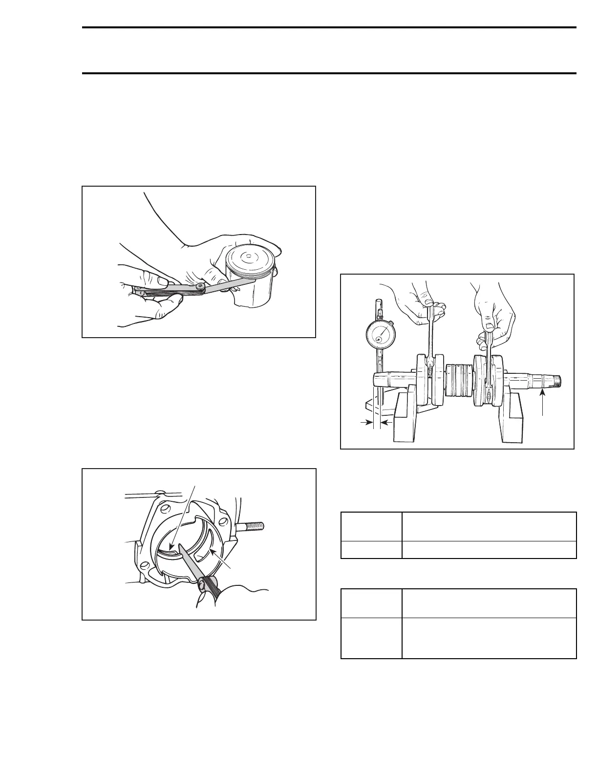
CRANKSHAFT DEFLECTION
Crankshaft deflection is measured with a dial indi-
cator.
Measuring (in crankcase)
First, check deflection with crankshaft in
crankcase. If deflection exceeds the specified tol-
erance, recheck deflection using V-shaped blocks
to determine the defective part(s). See below.
Measuring (on bench)
Once engine is disassembled, check crankshaft
deflection on V-shaped blocks. If deflection
exceeds the specified tolerance, it can be worn
bearings or a bent crankshaft. Remove crankshaft
bearings and check deflection again on V-shaped
blocks to determine the defective part(s). See
measurement A in following illustration.
A01C0RD
1
A
TYPICAL
1. Measure at mid point between the key and the first thread
A. 3mm(1/8in)
Crankshaft Deflection on PTO Side
ENGINE
TYPE
MAXIMUM ON PTO SIDE
mm (in)
All 0.06 (.0024)
Crankshaft Deflection on MAG Side
ENGINE
TYPE
MAXIMUM ON MAG SIDE
mm (in)
593, 593
HO/SDI,
793 HO
0.05 (.002)
mmr2004-Rev 119

 Loading...
