Section 06 TRANSMISSION
Subsection 02 (DRIVE PULLEY)
6,25,29, Sliding Half, Slider Shoe
and Governor Cup
To install governor cup, use following tool:
A16B01A
529 005 500
Insert spring and slider shoes into governor cup
so that groove in each slider shoe is vertical to
properly slide in guides.
CAUTION: Make sure O-rings are installed on
slider shoes and that grooves are positioned
vertically.
Install fork (P/N 529 005 500) into slider shoe
grooves to maintain them for governor cup instal-
lation. Proceed on 3 set of slider shoes.
A16B02A
529 005 500
TYPICAL
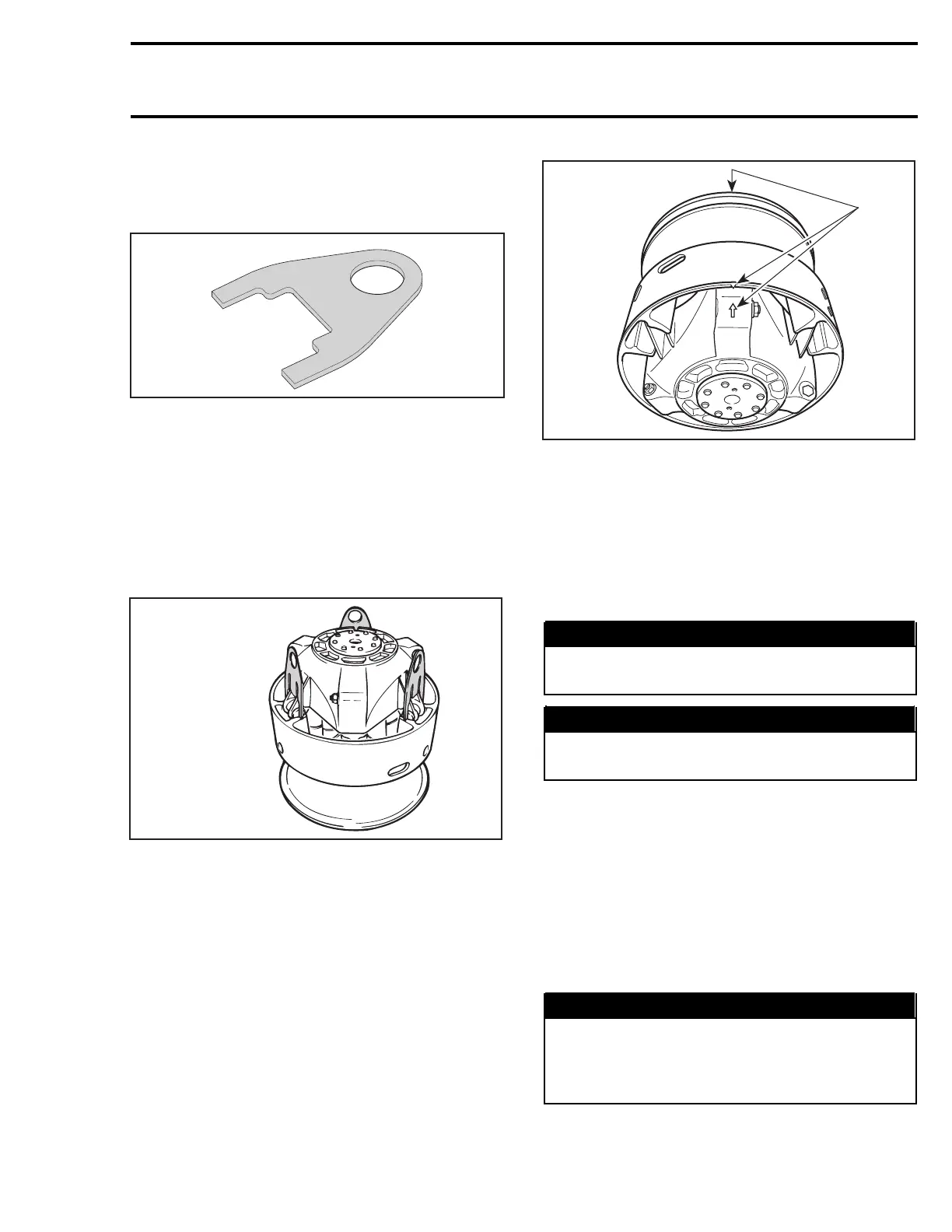
Make sure to align governor cup arrow with sliding
half and fixed half mark.
NOTE: If fixed half has no mark, align governor
cup mark with segment no. 1 of inner half.Seg-
ments are identified on engine side.
A16D0EA
1
TYPICAL
1. Align
Carefully slide governor cup into sliding half. Align
mark of governor cup with mark of fixed half.
Remove forks and push governor cup so that its
splines engage with fixed half shaft splines.
INSTALLATION
WARNING
Do not apply anti-seize or any lubricant on
crankshaft and drive pulley tapers.
WARNING
Never use any type of impact wrench at drive
pulley removal and installation.
Clean mounting surfaces as described in CLEAN-
ING above.
Drive Pulley Ass’y
The following installation procedure must be
strictly adhered.
Install drive pulley on crankshaft extension.
Install a new conical spring washer with its con-
cave side towards drive pulley then install screw.
WARNING
Never substitute conical spring washer
and/or screw with jobber ones. Always use
Bombardier genuine parts for this particular
case.
Use holder. See removal procedure.
mmr2004-Rev 223

 Loading...
