Section 08 REAR SUSPENSION
Subsection 02 (SC-10 III SUSPENSION)
1
A01B4LA
2
3
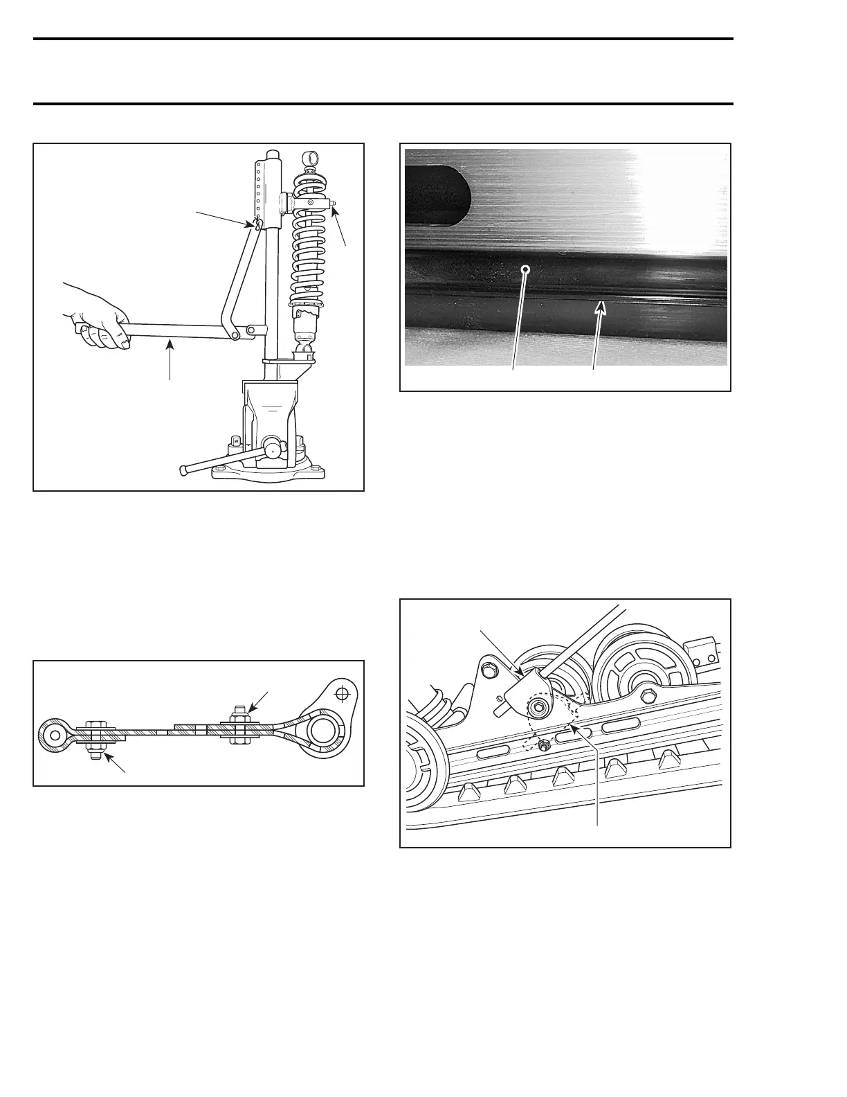
1. Clevis pin
2. Bar
3. Handle horizontal
Stopper Strap
Inspect strap no. 10 for wear or cracks, bolt and
nut for tightness. If loose, inspect hole for defor-
mation. Replace as required. Make sure it is at-
tached through proper holes. Torque nut to 7 N•m
(62 lbf•in).
A
A32F17A
A
A. 7 N•m(62lbf•in)
Slider Shoe
Molding line is the wear limit indicator.
1
A03F3SA
2
TYPICAL
1. Slider shoe
2. Molding line (wear limit indicator)
Replace slider shoes no. 11 when wear limit is
reached.
CAUTION: Slider shoes must always be re-
placed in pairs.
Spring Support
CAUTION: To avoid track damage, spring sup-
ports no. 12 must be mounted upward.
A03F0VA
1
2
TYPICAL — RIGHTSIDESHOWN
1. Right position: upward
2. Wrong position
SHOCK ABSORBER INSPECTION
All Models Equipped with Hydraulic Shock
NOTE: Hydraulic shocks are painted black or dark
gray.
300 mmr2004-Rev

 Loading...
