Section 05 2–TEC ENGINE MANAGEMENT
Subsection 02 (COMPONENT INSPECTION AND ADJUSTMENT)
VALUE
ENGINE TYPE
AT SEA LEVEL
ABOVE 1800 m
(6000 ft)
593 SDI
3.9° 4.1°
If throttle cable has been loosen during the proce-
dure, adjust a throttle cable.
Start engine and make sure it operates normally
through its full engine RPM range. If fault codes
appear, refer to SYSTEM FAULT CODES in the DI-
AGNOSTIC PROCEDURES section for more infor-
mation.
CRANKSHAFT POSITION
SENSOR (CPS)
NOTE: The CPS is the trigger coil used for forward
and reverse.
1
A32C9UA
1. CPS connector
NOTE: Take into account that a CPS fault can be
triggered by missing encoder wheel teeth. First
check fault codes then check the teeth condition
if necessary. See below.
Disconnect CPS wiring harness connector. Probe
terminals coming from CPS while cranking engine.
Voltage should be within 1-2 Vac. Otherwise, in-
spect wiring and replace CPS if wiring is good.
Resistance Test
Disconnect the CPS plug connector from the
wiring harness and check the resistance of the
sensor itself.
The resistance should be between 190
and
300
.
Otherwise, replace the CPS.
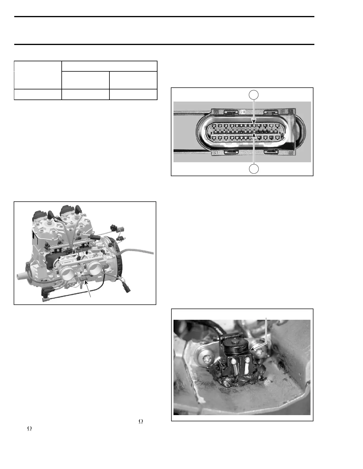
If resistance tests good, reconnect the CPS and
disconnect the connector DA on the ECM.
R1503motr182A
5
19
Using a multimeter, recheck resistance value be-
tween terminals 5 and 19.
If resistance value is correct, try a new ECM. Refer
to ECM REPLACEMENT procedures elsewhere in
this section.
NOTE: Check if wiring harness shows any signs
of scoring prior to replace the ECM.
If resistance value is incorrect, repair the connec-
tors or replace the wiring harness between ECM
connector and the CPS.
Replacement
Disconnect connectors and remove the rewind
starter, then the magneto flywheel. Refer to
MAGNETO SYSTEM.
Remove CPS.
1
A32C9VA
1. CPS inside crankcase
192 mmr2004-Rev

 Loading...
