Section052–TEC ENGINE MANAGEMENT
Subsection 02 (COMPONENT INSPECTION AND ADJUSTMENT)
NOTE: When measuring between pins DA-24 and
DA-39, resistance value increases while depress-
ing throttle lever. When measuring between pins
DA-24 and DA-25, resistance value decreases
while depressing throttle lever. The resistance
value should change smoothly and proportionally
to the throttle movement. Otherwise, replace
TPS.
If resistance values are correct, try a new ECM.
Refer to ECM REPLACEMENT procedures else-
where in this section.
NOTE: Check if wiring harness shows any signs
of scoring prior to replace the ECM.
If resistance values are incorrect, repair connector
or replace the wiring harness between ECM con-
nector and the TPS.
Replacement
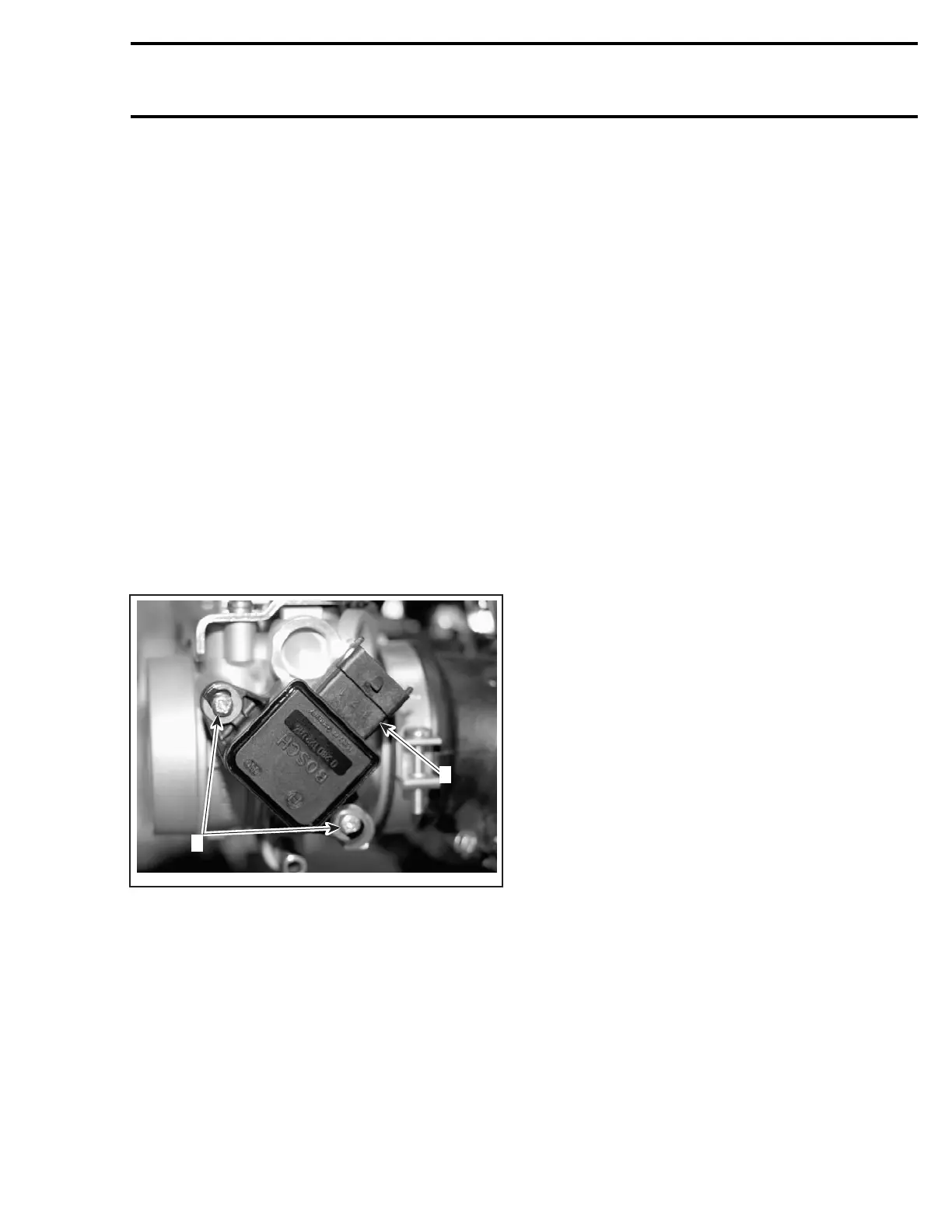
Remove the throttle body as described above.
Loosen two screws retaining the TPS.
Remove TPS.
A32C9RB
1
2
THROTTLE BODY
1. Throttle position sensor (TPS)
2. Screws
Install the new TPS.
Apply Loctite 243 on the TPS retaining screws,
then torque to 3 N•m(27lbf•in).
Reinstall remaining removed parts.
ProceedwiththeClosed Throttle Reset.Seebe-
low.
Closed Throttle Reset
NOTE: This operation performs a reset of the val-
ues in the ECM.
This reset is very important. The setting of the
TPS will determine the basic parameters for all
fuel mapping and several ECM calculations in idle
speed control of the engine.
NOTE: Resetmustbedoneeachtimethethrottle
position sensor (TPS) is loosened or removed or
throttle body or ECM is replaced.
CAUTION: An improperly set TPS may lead to
poor engine performance.
Use the vehicle communication kit (VCK) with the
B.U.D.S. software to perform this adjustment.
Unscrew idle speed screw until the throttle body
plate stop lever rest against its zero position stop-
per screw (capped screw). If necessary, loosen
the throttle cable. Open throttle approximately
one quarter then quickly release. Repeat 2 - 3
times to settle throttle plate.
Push the Reset buttonintheSetting section of
B.U.D.S.
The following message will be displayed:
Make sure the idle screw is not in contact with the
throttle stopper. Click OK to continue.
Follow instructions and click OK.
Another message will appear to ask you to per-
form a ECU tracking shut down to save the
changes into the ECU permanent memory.
Remove the tether cord cap from the DESS post
and wait until the message disappears before rein-
serting the tether cord cap.
Re-power up the ECM by pushing the START/RER
button momentarily.
The throttle opening displayed in B.U.D.S. should
be 0.00 (0.05 maximum).
If TPS is not within the allowed range while reset-
ting the Closed Throttle, the ECM will generate a
fault code and will not accept the setting.
Now, the idle speed screw has to be adjusted.
To do this, screw in the idle speed screw until
B.U.D.S. throttle opening displays value as per fol-
lowing table.
mmr2004-Rev 191

 Loading...
