Section 05 2–TEC ENGINE MANAGEMENT
Subsection 02 (COMPONENT INSPECTION AND ADJUSTMENT)
The ECM may generate several fault codes per-
taining to the TPS. Refer to SYSTEM FAULT
CODES in DIAGNOSTIC PROCEDURES section
for more information.
Wear Test
While engine is not running, activate throttle and
pay attention for smooth operation without physi-
cal stops of the cable.
Using the vehicle communication kit (VCK) with
the B.U.D.S. software, use the Throttle Opening
display under Monitoring.
Slowly and regularly depress the throttle. Ob-
serve the needle movement. It must change
gradually and regularly as you move the throttle.
If the needle “sticks”, bounces, suddenly drops
or if any discrepancy between the throttle move-
ment and the needle movement is noticed, it
indicates a worn TPS that needs to be replaced.
Voltage Test
Check the voltage output from ECM to the desired
throttle position sensor.
3
A32C9SA
21
TPS
Disconnect plug connector from throttle position
sensor. To unlock connector, insert a small screw-
driver between the folded tab. To see the con-
nector pin-out and its pin numbers, temporarily re-
move the connector shield joining the harness.
Install the tether cord cap, turn OFF engine cut-out
switch and push START/RER button momentarily
to activate the ECM.
Connect a voltmeter between pin 1 and 2 in the
wiring harness.
Voltageshouldbe5V.
Checkthecontinuitybetweenpin3onwiringhar-
ness TPS connector and pin 24 on wiring harness
ECM connector.
If tests are good, replace the TPS.
If voltage tests are not good, continue to check
the resistance of the rest of the TPS circuit.
Resistance Test
Reconnect the TPS.
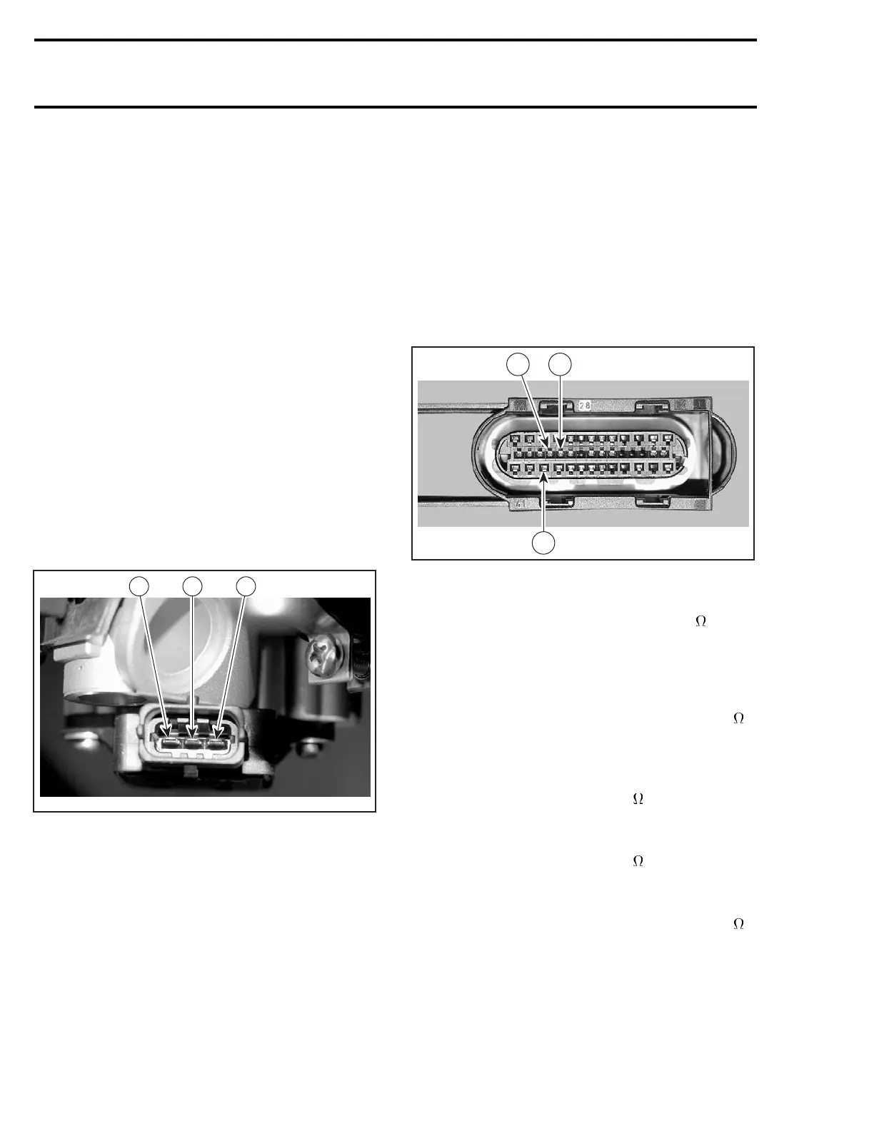
Disconnect the connector DA from the ECM.
R1503motr191A
24
39
25
Using a multimeter, check resistance value be-
tween terminal DA-25 and DA-39.
The resistance should be 1600 - 2400
in any
throttle position.
Check the resistance between terminal DA-24 and
terminal DA-39 with the throttle plate in idle posi-
tion.
The resistance should be approximately 1000
.
Check the resistance between terminal DA-24
and terminal DA-39 with the throttle plate in wide
open position.
Theresistanceshouldbe2500
.
Check the resistance between terminal DA-24 and
DA-25 with throttle plate in idle position.
Theresistanceshouldbe2500
.
Now check the resistance with the throttle plate
in wide open position.
The resistance should be approximately 1000
.
190 mmr2004-Rev

 Loading...
