Section 08 REAR SUSPENSION
Subsection 02 (SC-10 III SUSPENSION)
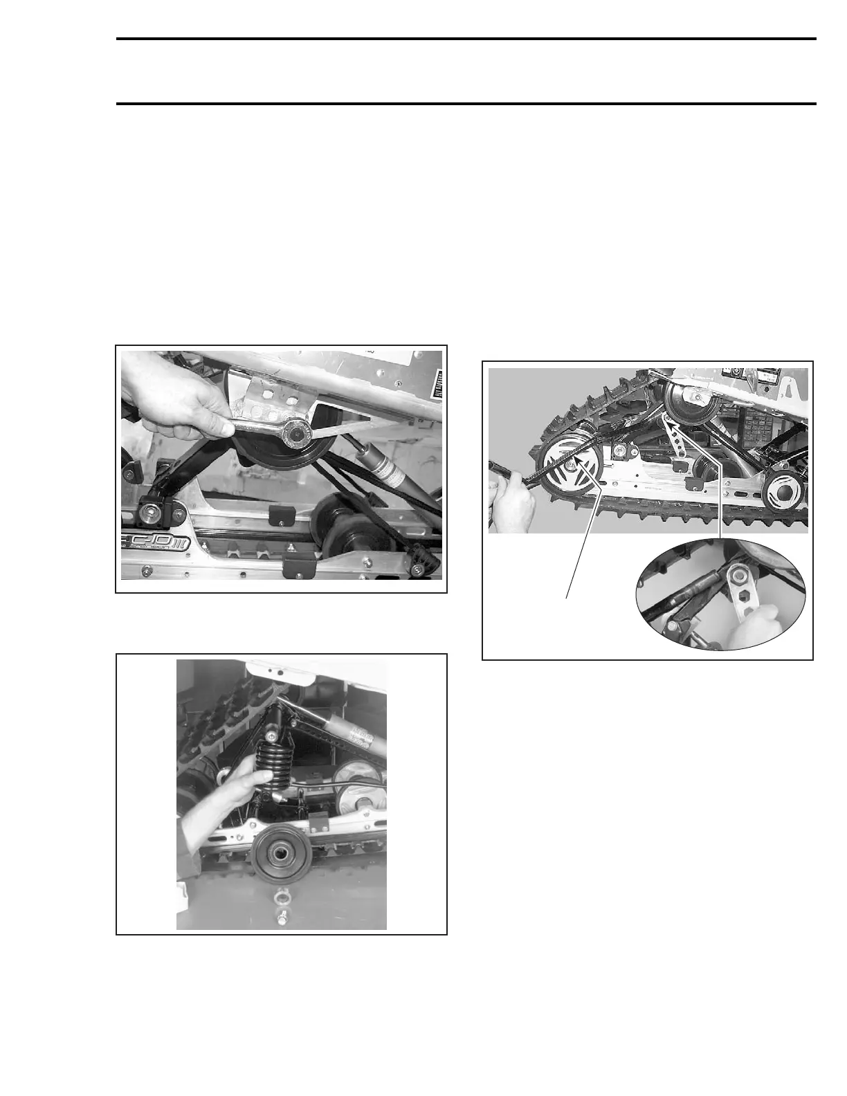
Rear Spring
Decrease spring preload by turning cams no. 19
accordingly.
Slightly turn adjusting cam to expose spring end.
Using spring installer (P/N 529 005 000), remove
both springs from adjusting cams.
Remove spring ends from adjusting cams.
Unbolt rear arm top axle from chassis.
Unscrew set screws from locking ring at each end
of top axle.
A33F45A
Remove spacers and top idler wheels.
Remove springs no. 22.
A03F1QA
TYPICAL
At reassembly, respect THIS SIDE OUT inscription
on wheel.
SUSPENSION ASSEMBLY
REMOVAL
Cam
Lift rear of vehicle and support it off the ground.
Loosen track tension.
Decrease spring preload by turning cams no. 19
accordingly.
Slightly turn adjusting cam to expose spring end.
Using spring installer (P/N 529 005 000), remove
both springs from adjusting cams.
529 005 000
A33F43A
Self-Locking Screws
CAUTION: These self-locking screws must al-
ways be replaced by new ones everytime they
are removed.
NOTE: To prevent axle from turning when un-
screwing self-locking screws no. 1, no. 2, no. 3,
no. 4, no. 5, no. 6, proceed as follows:
– Remove one self-locking screw then install a
10 mm shorter non-self-locking one in place.
Torque as specified in exploded view.
– Remove the opposite self-locking screw.
– Remove the temporary installed non-self-lock-
ing screw.
– If it doesn’t work, heat bolt head to melt thread-
locker.
Remove rear arm top axle self-locking screws
no. 1 from chassis.
mmr2004-Rev 297

 Loading...
