Section 08 REAR SUSPENSION
Subsection 01 (SC-10 SUSPENSION)
A32F3DA
A
1
2
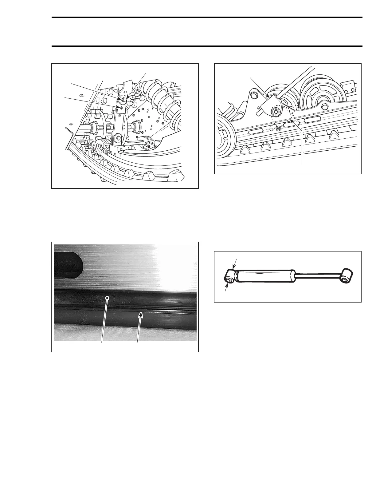
ALL MODELS EXCEPT SUMMIT LIQUID COOLED MODELS
1. 1
st
hole
2. 2
nd
hole
A. 7 N•m(62lbf•
in)
Slider Shoe
Molding line is the wear limit indicator.
1
A03F3SA
2
TYPICAL
1. Slider shoe
2. Molding line (wear limit indicator)
Replace slider shoes no. 17 when wear limit is
reached.
CAUTION: Slider shoes must always be re-
placed in pairs.
Spring Support
CAUTION: To avoid track damage, spring sup-
ports no. 18 must be mounted upward.
A03F0VA
1
2
RIGHTSIDESHOWN
1. Right position: upward
2. Wrong position
SHOCK ABSORBER INSPECTION
All Models Equipped with Hydraulic Shock
NOTE: Hydraulic shocks are painted black.
Secure the shock body end in a vise with its rod
upward.
A14F0BA
1
1. Clamp
CAUTION: Do not clamp directly on shock
body.
Examine each shock for leaks. Extend and com-
press the piston several times over its entire
stroke. Check that it moves smoothly and with
uniform resistance with its rod upward.
Pay attention to the following conditions which
will denote a defective shock:
– A skip or a hang back when reversing stroke at
mid travel.
– Seizing or binding condition except at extreme
end of either stroke.
– Oil leakage.
– A gurgling noise, after completing one full com-
pression and extension stroke.
mmr2004-Rev 291

 Loading...
