Section 09 STEERING/FRONT SUSPENSION
Subsection 01 (STEERING SYSTEM)
Reinstall terminals and replug connectors. Test
grips to ensure they heat properly.
Steering Column
Unfasten windshield. Remove cap no. 3 or steer-
ing padding no. 23 according to model.
Remove console. Refer to STEERING COLUMN
POSITION ADJUSTMENT below.
Cut locking ties retaining harnesses to steering
column no. 1.
Unbolt handlebar ass’y and move it aside.
Remove tuned pipe.
Detach the short tie rod no. 8 from the steering
column. Note that a hardened flat washer no. 7
goes on each side of steering column lever.
Disengage carriage bolts no. 6 from steering
column support no. 15. Remove lower plastic
U-clamps from steering column.
Disengage carriage bolts no. 5 from steering sup-
port. Remove upper plastic U-clamps from steer-
ing column.
Pull steering column from top.
If, for any reason, the master cylinder has been
removed from handlebar note that its clamp
no. 27 must be installed with the embossed
arrow pointing downward. Torque screws to 8
N•m(71lbf•in) beginning with the bottom screw.
1
A33D0ZA
2
1. Arrow on clamp pointing downward
2. Tighten bottom screw first
Refer to HANDLEBAR POSITION ADJUSTMENT
for handlebar reinstallation.
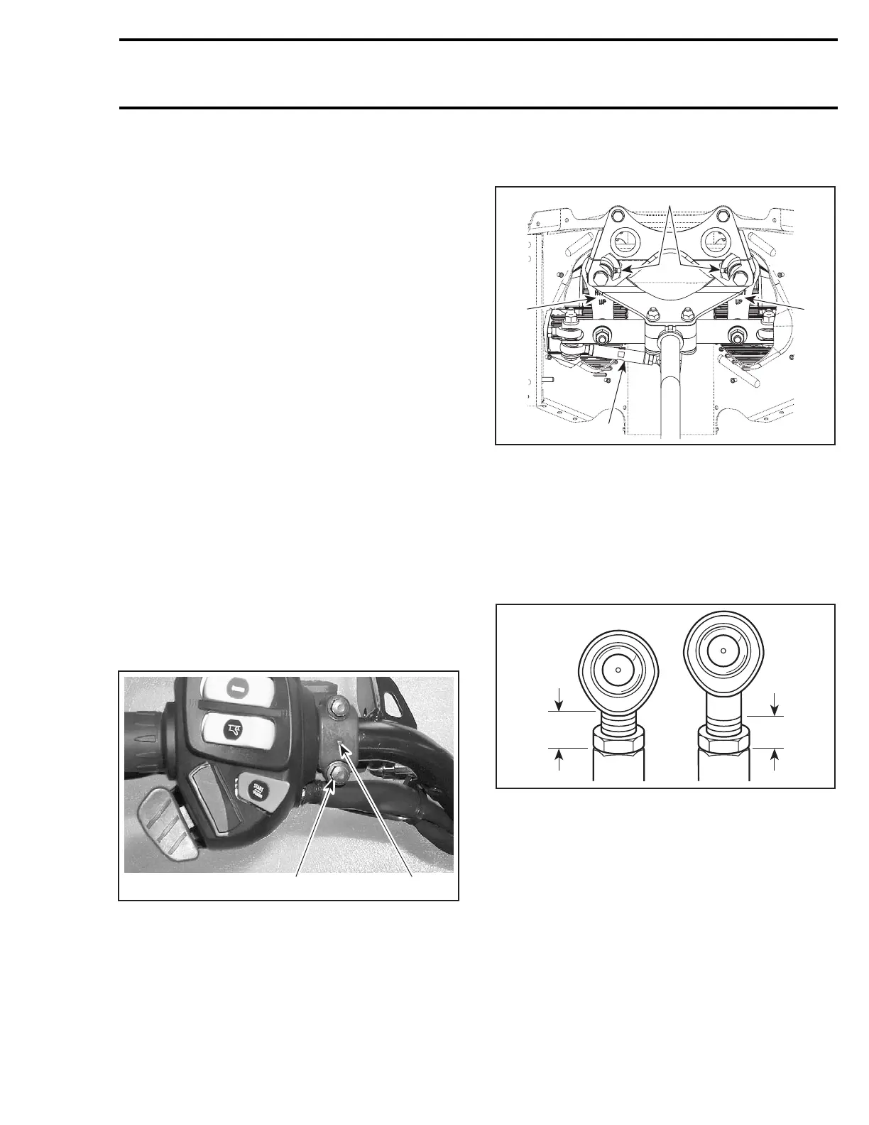
RH and LH Swivel Arm
At assembly respect UP mention.
Grease fitting no. 16 of swivel arms no. 14 must
face toward center of vehicle.
1
2
A33G0DB
1
3
1. UP mention
2. Grease fittings
3. Small tie rod
Ball Joint (left hand and right
hand threads)
The maximum external threaded length not en-
gaged in the tie rod must not exceed 20 mm
(25/32 in).
A02G0SA
A
A
TYPICAL
A. 20 mm (25/32 in) max.
The ball joint no. 17 and no. 18 should be re-
strained when tightening the tie rod end lock nut.
Align it so the tie rod end is parallel to the steering
arm when assembled on the vehicle, refer to the
following illustration.
For proper torque specifications refer to the spe-
cific exploded view for the vehicle being serviced.
mmr2004-Rev 325

 Loading...
