Section 05 2–TEC ENGINE MANAGEMENT
Subsection 02 (COMPONENT INSPECTION AND ADJUSTMENT)
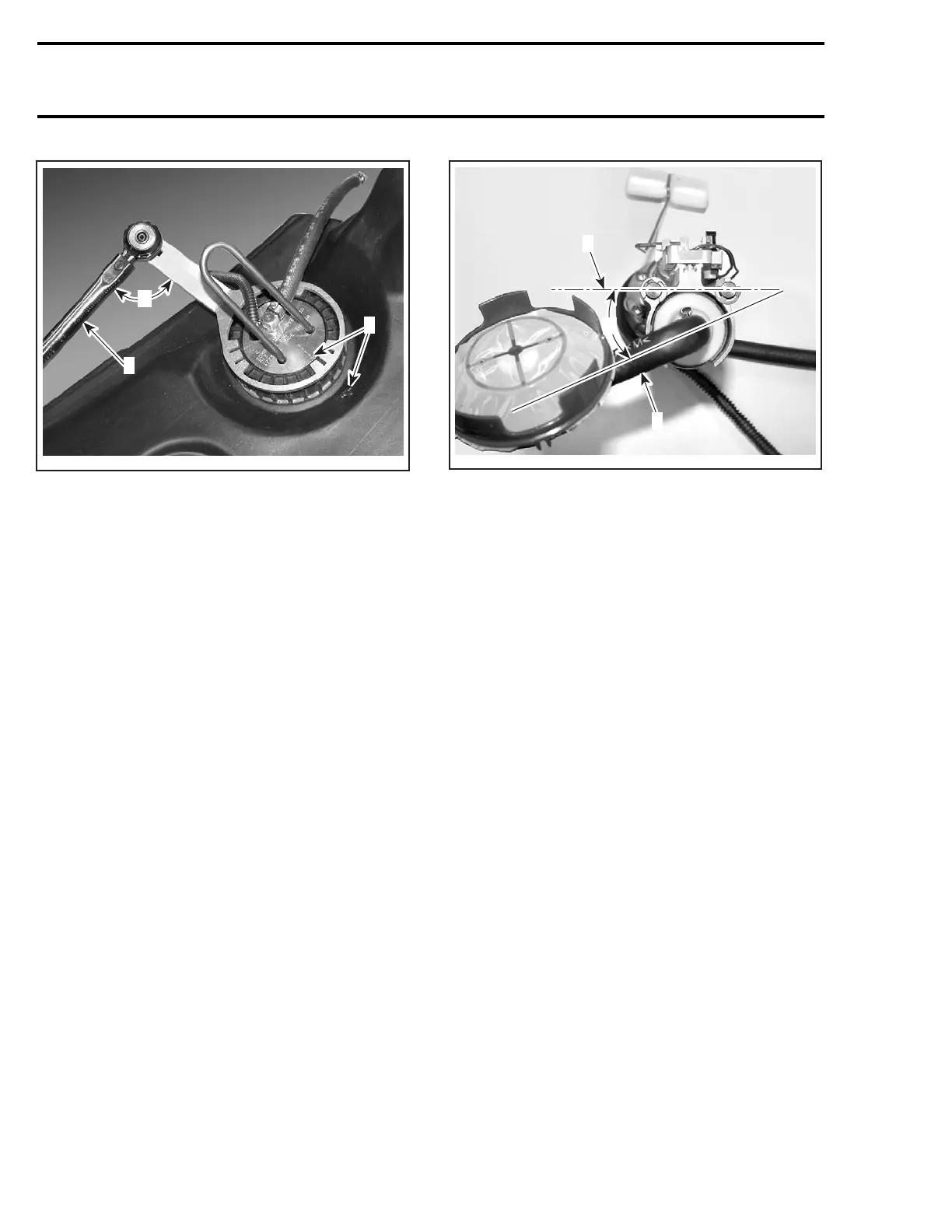
A32I1BA
2
A
1
1. Arrows
2. Torque wrench
A. 90°
Bleed the fuel system as following procedure.
Fuel Bleeding Procedure
The rear fuel pickup hose has to be bled.
Pour 12 L (3.17 U.S. gal.) of recommended fuel in
the fuel tank.
Apply parking brake. Start the engine. Let it run
at idle speed.
Lift the front of vehicle at a 45° angle.
Put the vehicle back on the ground.
Do the above procedure three times.
Stop the engine. The rear fuel pickup hose is now
bled.
Fuel Hose Kit (P/N 861 302 400)
Remove fuel pump module as explained above.
Unfasten blue hose clamp retaining old fuel hose
ass’y to pump inlet nipple. Remove old fuel hose
ass’y.
Install fuel hose ass’ytopumpatanangleof17°
±3° from retaining rods axis.
A33I0FA
A
1
2
1. Retaining rods axis
2. Fuel hose ass’y
A. 17° ±3°
Install a new blue hose clamp on fuel hose ass’y.
Install a new gasket, then reinstall fuel pump mod-
ule as explained above.
Float and Resistor Card Ass’yKit
(P/N 861 302 500)
Remove fuel pump module as explained above.
Loosen screw retaining lock plate. Slide lock plate
outofaluminumextrusion.
Cut locking tie retaining electric connectors of re-
sistor card ass’y. Unplug the connectors.
Slide old float and resistor card ass’y out of alu-
minum extrusion.
Assemble the new float to the new resistor card.
Installer the retainer.
Slide new float and resistor card ass’yinaluminum
extrusion.
184 mmr2004-Rev

 Loading...
