Section07ELECTRICALSYSTEM
Subsection 05 (TESTING PROCEDURE)
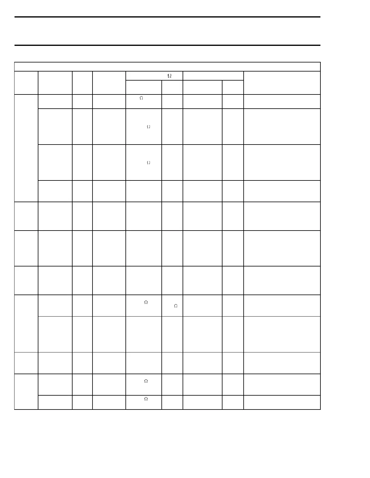
360 W MODEL (ignition and electrical system testing)
RESISTANCE VOLTAGE V
PART
TEST TO BE
PERFORMED
WIRE
COLOR
MULTIMETER
PROBE
CONNECTION
MULTIMETER
SCALE
VALUE
(ohms)
MULTIMETER
SCALE
VALUE
(volt)
NOTE
Primary winding
resistance
WH/BU
and BK
11–DC-2–F
11–DC-1–F
00.0 or auto
range
00.2 to 0.5 — —
Disconnect the ignition coil from
the MPEM
Secondary
winding
resistance spark
plug wires and
cap included
Between
both
spark
plug caps
Between both
spark plug caps
00.0
14.5 k to
23.5 k
— —
Do not attempt to remove spark plug
caps from the wires.
Secondary
winding
resistance spark
plug wires
removed
Male
terminal
to male
terminal
On male
terminals of high
voltage coil
00.0
9.6 k to
14.4 k
— —
With spark plug wires removed from
high voltage coil.
High
voltage coil
Secondary
winding voltage
BK and
engine
On spark plug
wire insulation
and on engine
— — 00.0 Vdc 1.5to2.5
Do not probe into spark plug cap with
spark plug wire removed from spark plug.
Start/RER
switch
(with
battery)
Start/RER signal
at MPEM
BE and
BK
11–DA-7–F
11–DA-3–F
— — 00.0 Vdc
Battery
voltage
When start/RER switch is activated
in all conditions.
Charging
voltage
Battery voltage
to switch from
5Afuse
RD/GY
and
negative
battery
terminal
12–HG-5 and
negative battery
terminal
— — 00.0 Vdc
Battery
voltage
The 5 A fuse is located on the
electrical config harness.
Start/RER
switch
(without
battery)
RER signal at
MPEM
BE/BK
11–DA-7–F
11–DA-3–F
— — 00.0 Vdc
11 to 13
volts
When RER button is activated and
the engine is running.
Continuity from
start/RER switch
to MPEM
BE and BE
12–HG-8–M
11–DA-7–F
00.0 or
autorange
1.0 — — —
Start/RER
switch (all)
Voltage supply
from regulator
RD/BU
and
negative
battery
terminal
5–RR-87–F and
negative battery
terminal
— —
Above battery
voltage below 15
volts
00.0 Vdc —
Charging
current
Current to battery
RD and
RD/WH
6–FA-A-F
6–FA-B-F
— — 10 A scale 2–4 A
Engine @ 5000 RPM with fully charged
battery. With 30 A fuse removed
and ammeter in series.
Output
YL and YL
and GN
2–MO-(1, 2, 3)-F
00.0 or
autorange
00.0 to
00.5
3times
00.0 Vac
3.5 to 5.5
3times
Do the test between A and B, A and C
and B and C using manual starter.
Lighting
generator
coil
Coil insulation
YL and
engine
2–MO-(1, 2, 3)-F
and engine
00.0 or
autorange
0.L — —
The term engine refers to the metal parts
connected to the magneto housing.
282 mmr2004-Rev

 Loading...
