Section 05 2–TEC ENGINE MANAGEMENT
Subsection 02 (COMPONENT INSPECTION AND ADJUSTMENT)
3
A32CA5A
2
1
Install tether cord cap on the DESS post and push
the START/RER button momentarily to activate
the ECM.
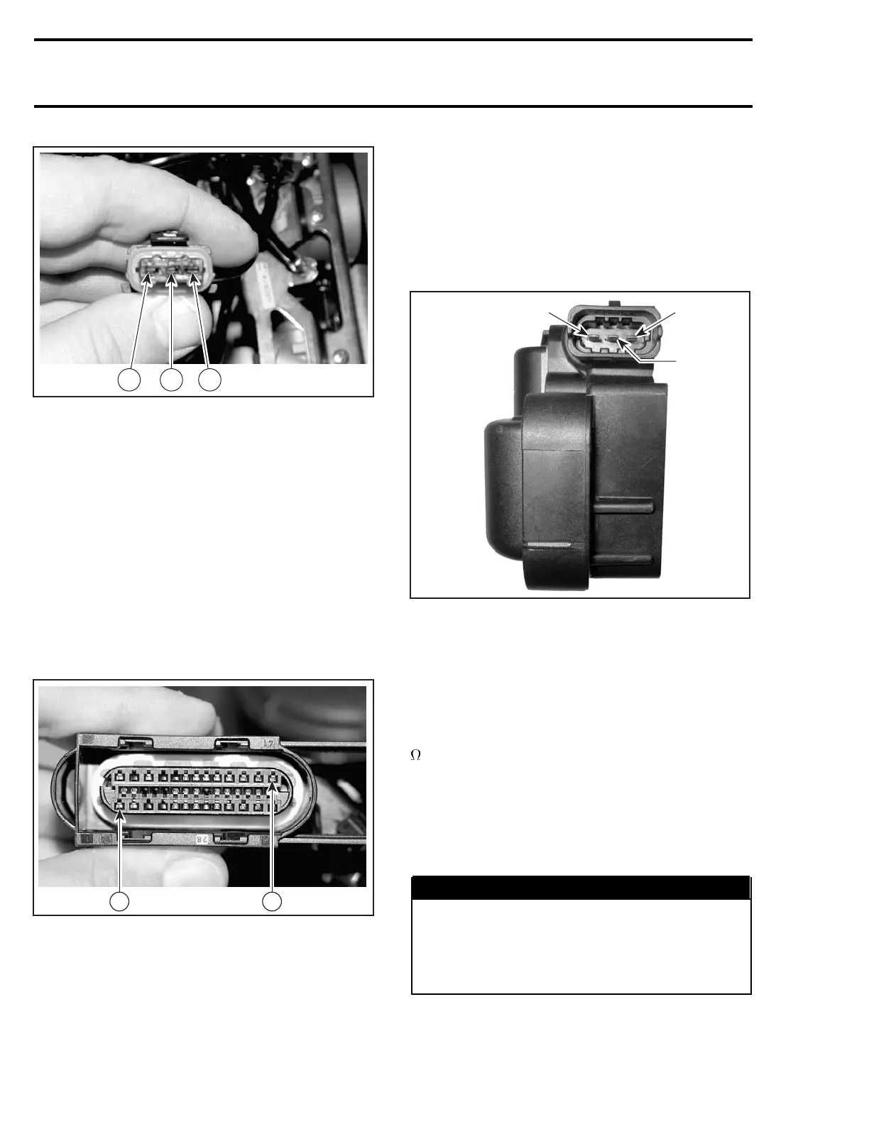
Check voltage between terminal 2 of ignition
coil connector on the wiring harness and battery
ground.
Battery voltage should be present (approx. 12 V).
If 12 V is NOT read, check continuity between ter-
minal 2 of ignition coil and the corresponding fuse.
Otherwise repair wiring harness.
If 12 V is read, disconnect the connector A from
the ECM and check the continuity of appropriate
circuit 41 (cylinder 1) or 1 (cylinder 2) and of ignition
coil connector, pin 3 and pin 1 respectively.
A32C9NC
41
1
ECM CONNECTOR
If wiring harness is defective, repair the connector
or replace the wiring harness between ECM con-
nector and the ignition coil.
If wiring harness is good, test resistance of pri-
mary winding of ignition coil.
Resistance Test
Remove spark plug cables from ignition coil.
Using a multimeter, check the resistance of pri-
mary winding.
NOTE: The secondary winding can not be mea-
sured with an ohmmeter. Try a new double igni-
tion coil if necessary.
A32CCRA
3
2
1
1. Terminal 1a
2. Terminal 15
3. Terminal 1b
For primary winding, check the resistance be-
tween terminal 15 and terminal 1a (cylinder 1)
of the ignition coil and between terminal 15 and
terminal 1b (cylinder 2) respectively.
The resistance should be between 0.40 and 1.15
at 20°C(68°F).
If the resistance of one of both windings is not
good, replace the ignition coil.
If the windings test good, try a new ECM.
NOTE: Check if wiring harness shows any signs
of scoring prior to replace the ECM.
WARNING
Always reconnect ignition coil cables at the
same spark plugs where they come from.
Otherwise, severe backfire may occur with
possible damage to exhaust system compo-
nents.
198 mmr2004-Rev

 Loading...
