Do you have a question about the Spacelabs BleaseSirius and is the answer not in the manual?
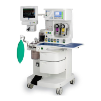
General overview of the BleaseSirius anesthetic machine, its design compliance, and major components.
Technical specifications including machine dimensions, work surface, monitor shelf, and maximum loading.
Details on gas-specific color specifications, supply combinations, and common gas outlet.
Performance specifications covering controls, ventilator, alarms, regulator settings, electrical, supplies, and environmental factors.
Detailed description of the ventilator's functions, modes, and parameters like PEEP, Trigger, and Volume Measurement.
Procedures for conducting pre-use tests including Fresh Gas, Compliance, Compensation, and Mode Dependant Features.
Explanation of the operational principles of the anesthetic machine and its components.
Guidelines for authorized technical engineers on servicing the machine safely and effectively.
Step-by-step instructions for routine maintenance tasks on seals, fittings, and components.
Procedures for cleaning external and internal surfaces of the anesthetic machine.
Lists necessary tools and test equipment for performing system checks.
Procedure to test for leaks in the gas pipeline connections.
Procedure to test for leaks in the gas cylinder connections.
Procedure to verify electrical safety and leakage current compliance.
General instructions for component removal and replacement, including outer case removal.
Procedures for servicing, calibrating, and replacing the mechanical hypoxic guard block.
General information and disassembly/assembly procedures for the absorber.
Procedures for servicing and installing major ventilator components.
Technical overview of the Electronic Flowmeter (EFM) option, including components and specifications.
Steps for replacing EFM components like hypoxic guard, display screen, circuit board, and flow sensors.
Using the EFM service application for software updates, configuration, and troubleshooting.
Lists error codes for Blease700/900 series ventilators with common causes and corrective actions.
Comprehensive list of spare parts including regional fittings, tubing, moldings, electrical, and pneumatic components.
User's responsibilities for safe installation, use, and maintenance of the Blease700/900 Series Ventilator.
Manufacturer's responsibilities regarding safety, reliability, and performance of the equipment.
Guidance for qualified technical engineers on servicing the equipment and manual limitations.
Important hazard information including warnings, cautions, and general safety advice.
Schematic diagram of the master pressure interface board.
Schematic diagram of the power supply board.
Schematic diagram of the controller board CPU.
Schematic diagram of the controller board analogue components.
| Brand | Spacelabs |
|---|---|
| Model | BleaseSirius |
| Category | Medical Equipment |
| Language | English |