217
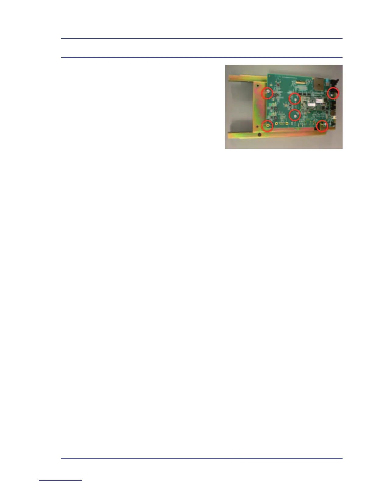
10. Remove the six screws that secure
the circuit board (Figure160).
11. Remove the circuit board assembly
and discard it.
12. Position the replacement circuit on
the EFM, then attach the six retaining
screws to secure the board (Figure
155).
13. Attach the three circuit board-screen
connectors.
14. Assemble the display screen over
the circuit board and attach the four retaining screws to secure the display
screen.
15. Connect the banjo fi tting to the side of the hypoxic guard.
16. Connect the four gas fl ow tubes to the EFM.
17. Connect the light pipe to the EFM circuit board.
18. Connect the ribbon cable and the power connector to the EFM.
19. Replace the EFM on the machine and secure it with the four retaining
screws [two on each side].
20. Replace the three system covers.
21. Power up the system to verify that the EFM is functional.
22. Use the Service Application to upload the EFM software and confi gure the
fl ow tubes.
EFM Option
Figure 160 - Circuit Board Screws
(6)