54
3.6.4 Fitting 4 Year Planned Maintenance Kit, PN 14000512
The recommended service intervals for the following are every 4 years. The
following procedure outlines the steps taken to replace the parts included in the
service kit 14200512.
3.6.5 Ventilator Filter
3.6.5.1 Two Valve Version Only (on units before Feb 2009)
1. Ensure all gas supplies are disconnected.
2. See Section 5.1 for removal of top surface and front cover.
3. Once the front cover is removed, you can access the 6 screws that secure
the top of the ventilator casing.
4. The front display panel will hinge forward a little. This will allow the top
cover to be hinged back.
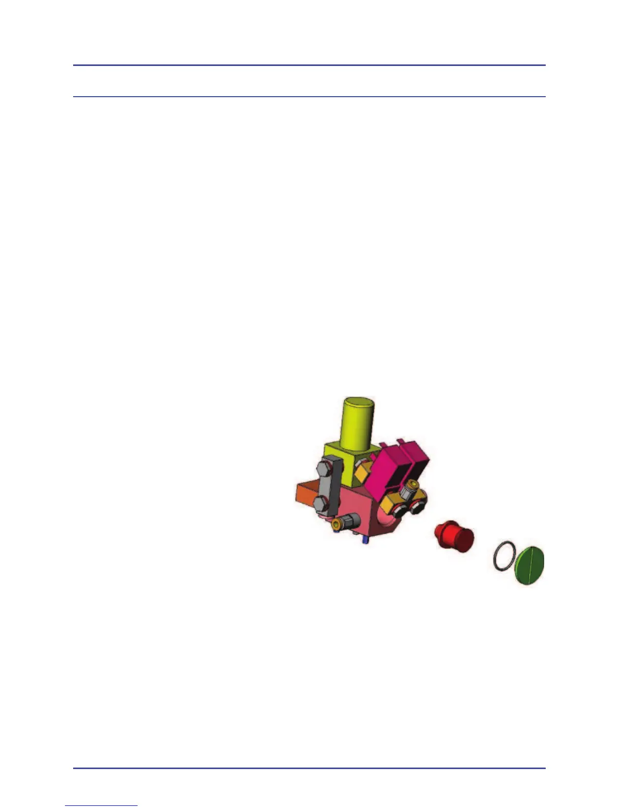
5. The fi ller cover is in the inlet manifold which can be seen from the front
of the unit.
6. Remove the cover.
7. The fi lter can then be
unscrewed.
8. Replace the fi lter and cover
and make sure the new ‘O’
ring is fi tted.
9. Replace the screws in the
top cover and front display
panel.
10. Reconnect the O
2
pipeline
only and turn on the system.
11. Check that there are no
leaks.
12. Turn the systems OFF.
13. Fit the front cover and top surface.
3.6.5.1 Valve Block on units after Feb 2009
Due to major enhancements in the inlet fi ltration methods, a valve block fi lter is
no longer required and, therefore, is not fi tted.
Figure 13 - Pneumatic Module
Planned Maintenance